2GR-FE ENGINE MECHANICAL – ENGINE ASSEMBLY
EM–45
EM
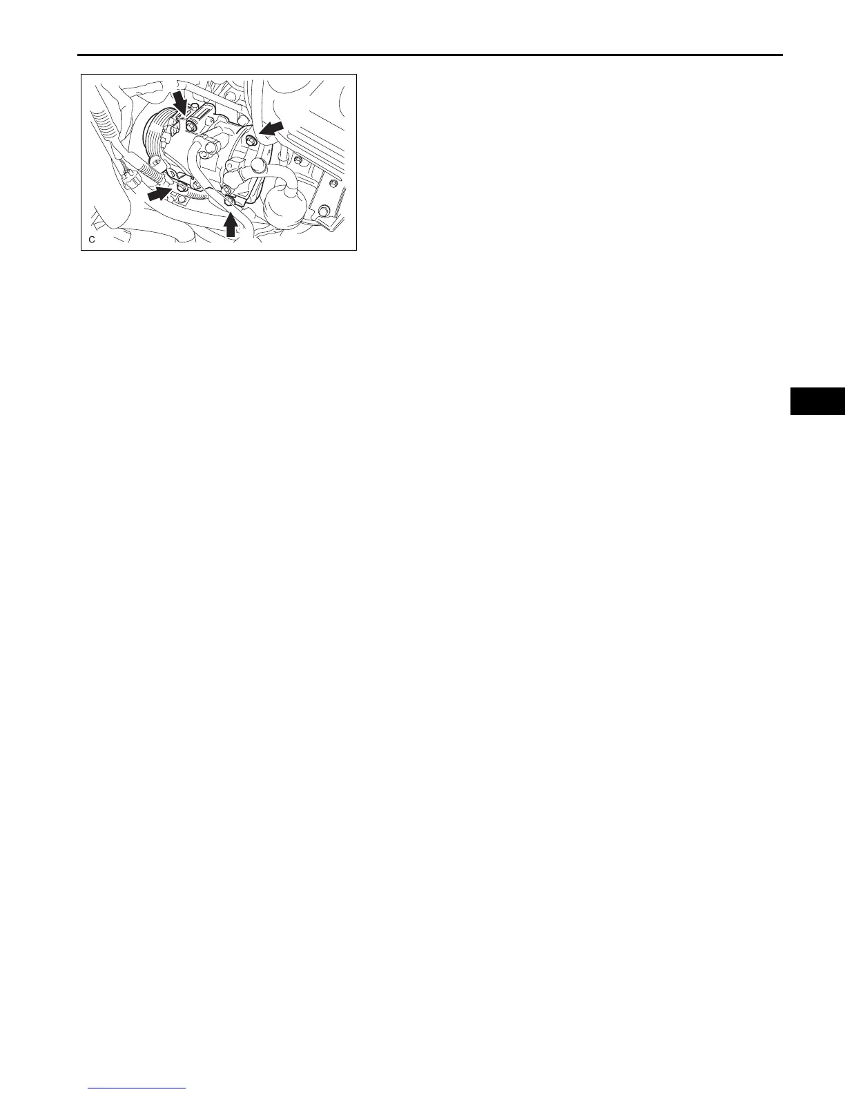
32. INSTALL COOLER COMPRESSOR ASSEMBLY
(a) Temporarily install the cooler compressor with the 4
bolts.
(b) Install the compressor with the 4 bolts by tightening
the bolts in the order shown in the illustration.
Torque: 25 N*m (250 kgf*cm, 18 ft.*lbf)
(c) Install the 2 connector clamps.
33. INSTALL GENERATOR ASSEMBLY (See page CH-22)
34. INSTALL STEERING SLIDING YOKE (See page PS-
65)
35. INSTALL DRIVE PLATE AND TORQUE CONVERTER
CLUTCH SETTING BOLT (See page AX-218)
36. INSTALL NO. 1 EXHAUST PIPE SUPPORT BRACKET
(a) Install the No. 1 exhaust pipe support bracket with
the bolt.
Torque: 21 N*m (214 kgf*cm, 15 ft.*lbf)
37. INSTALL FRONT AXLE ASSEMBLY LH (See page DS-
21)
38. INSTALL FRONT AXLE ASSEMBLY RH
HINT:
Use the same procedures described for the LH side.
39. INSTALL FRONT SUSPENSION LOWER NO. 1 ARM
LH (See page DS-21)
40. INSTALL FRONT SUSPENSION LOWER NO. 1 ARM
RH
HINT:
Use the same procedures described for the LH side.
41. INSTALL TIE ROD ASSEMBLY LH (See page DS-21)
42. INSTALL TIE ROD ASSEMBLY RH
HINT:
Use the same procedures described for the LH side.
43. INSTALL FRONT SPEED SENSOR LH (See page DS-
21)
44. INSTALL FRONT SPEED SENSOR RH
HINT:
Use the same procedures described for the LH side.
45. INSTALL FRONT STABILIZER LINK ASSEMBLY LH
(See page DS-22)
46. INSTALL FRONT STABILIZER LINK ASSEMBLY RH
HINT:
Use the same procedures described for the LH side.
47. INSTALL FRONT AXLE HUB NUT LH (See page DS-
22)
48. INSTALL FRONT AXLE HUB NUT RH
HINT:
Use the same procedures described for the LH side.
1
2
3
4
A132977E01
 Loading...