2GR-FE STARTING – SMART KEY SYSTEM
ST–41
ST
DESCRIPTION
This DTC is output when there is a problem in the IG2D output circuit, which is from the inside of the main
body ECU to the IG2 relay.
HINT:
When the main body ECU is replaced with a new one and the negative (-) battery terminal is connected,
the power source mode becomes the IG-ON mode. When the battery is removed and reinstalled, the
power source mode that was selected when the battery was removed is restored.
After the main body ECU is replaced, perform the registration procedures for the engine immobiliser
system (See page EI-8).
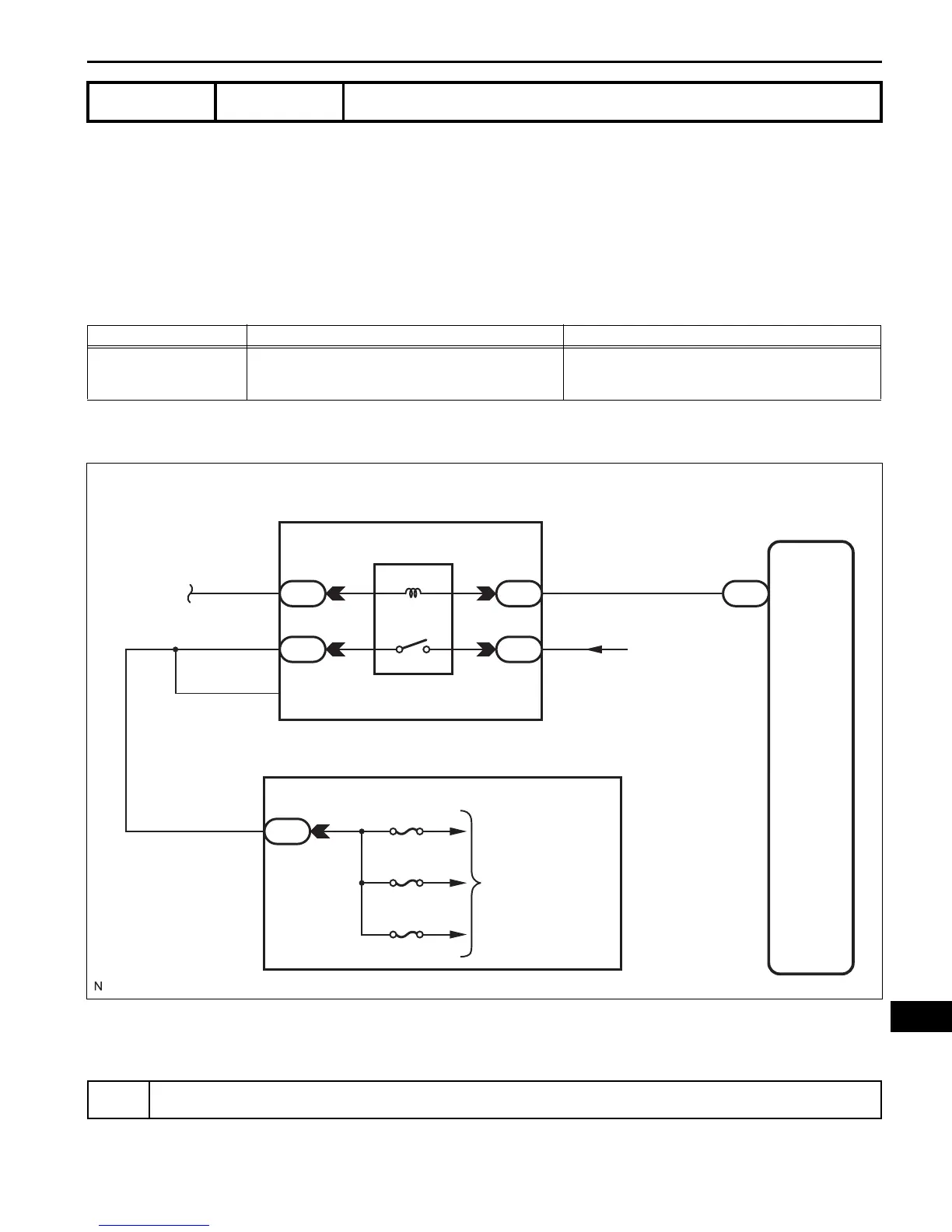
WIRING DIAGRAM
INSPECTION PROCEDURE
(a) Connect the intelligent tester to the DLC3.
DTC B2273 Ignition 2 Monitor Malfunction
DTC No. DTC Detection Condition Trouble Area
B2273
IG2 relay actuation circuit inside main body ECU or
other related circuit is malfunctioning
• Main body ECU
•IG2 relay
• Wire harness or connector
1
READ VALUE OF INTELLIGENT TESTER
Main Body ECU
IG2D
11
E6
From Battery
1
1
21
3
7
I1
5
1
1
Engine Room R/B
IG2 Relay
Instrument Panel J/B
GAUGE No. 2
IGN
INJ
To Each System
B137973E01
 Loading...