ES–252
2GR-FE ENGINE CONTROL SYSTEM – SFI SYSTEM
ES
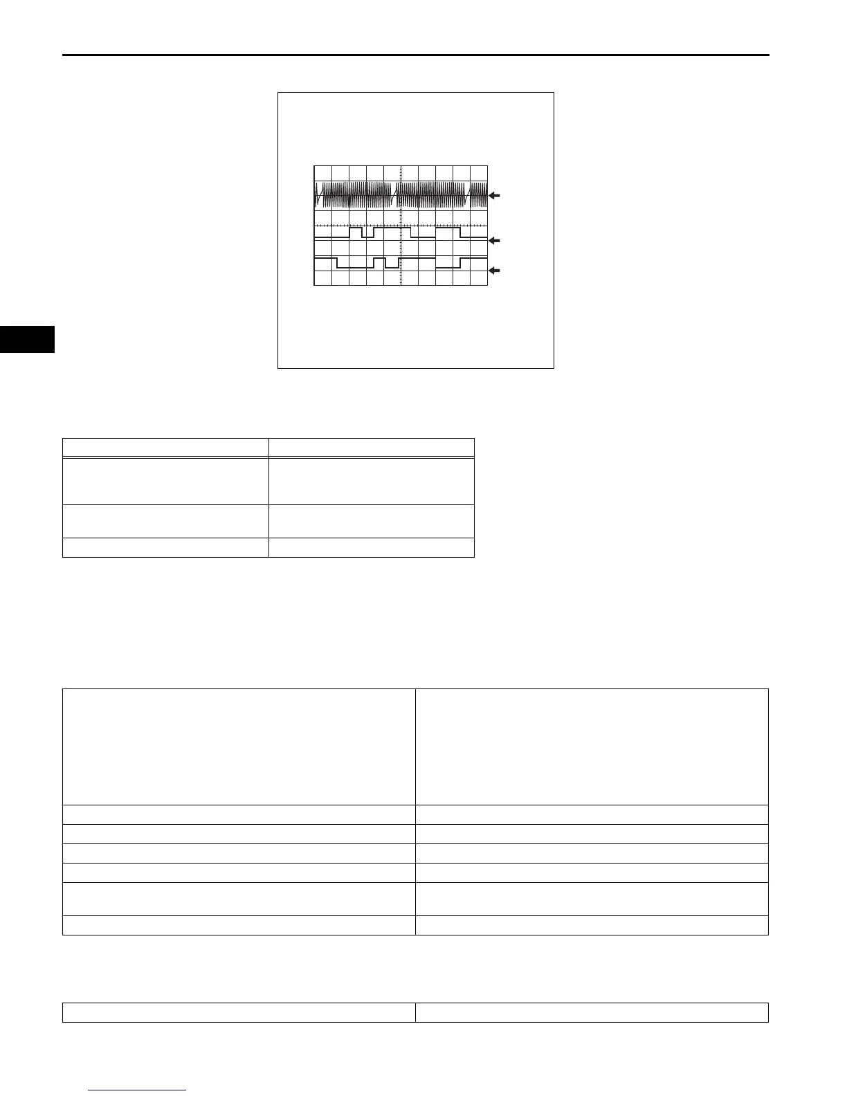
Reference: Inspection using an oscilloscope
HINT:
• The correct waveform is as shown.
• EV1+ and EV2+ stand for the VVT sensor signal, and NE+ stands for the CKP sensor signal.
MONITOR DESCRIPTION
If no signal is transmitted by the VVT sensor despite the engine revolving, or the rotations of the camshaft
and the crankshaft are not synchronized, the ECM interprets this as a malfunction of the sensor.
MONITOR STRATEGY
TYPICAL ENABLING CONDITIONS
All:
Item Content
Terminal
NE+ - NE-
EV1+ - EV1-
EV2+ - EV2-
Equipment Setting
5 V/DIV.
20 ms./DIV.
Condition Cranking or idling
Related DTCs
P0365: VVT sensor (Bank 1) open/short
P0365: VVT position/Crankshaft position misalignment (Bank 1)
P0367: VVT position sensor (Bank 1) range check (low voltage)
P0368: VVT position sensor (Bank 1) range check (high voltage)
P0390: VVT sensor (Bank 2) open/short
P0390: VVT position/Crankshaft position misalignment (Bank 2)
P0392: VVT position sensor (Bank 2) range check (low voltage)
P0393: VVT position sensor (Bank 2) range check (high voltage)
Required Sensors/Components (Main) VVT position sensor (Bank 1 and 2)
Required Sensors/Components (Sub) Crankshaft position sensor
Frequency of Operation Continuous
Duration 5 seconds
MIL Operation
2 driving cycles: P0365, P0390 (cranking)
Immediate: Others
Sequence of Operation None
Monitor runs whenever following DTCs are not present None
EV1, EV2 and NE Signal Waveform
NE
EV1
EV2
GND
GND
GND
5 V/DIV.
20 ms./DIV.
A140642E02
 Loading...