2GR-FE ENGINE CONTROL SYSTEM – SFI SYSTEM
ES–225
ES
MONITOR DESCRIPTION
The knock sensor, located on the cylinder block, detects spark knock. When spark knock occurs, the
piezoelectric element of the sensor vibrates. When the ECM detects a voltage in this frequency range, it
retards the ignition timing to suppress spark knock.
The ECM also senses background engine noise with the knock sensor and uses this noise to check for
faults in the sensor. If the knock sensor signal level is too low for more than 10 seconds, or if the knock
sensor output voltage is outside the normal range, the ECM interprets this as a fault in the knock sensor
and sets a DTC.
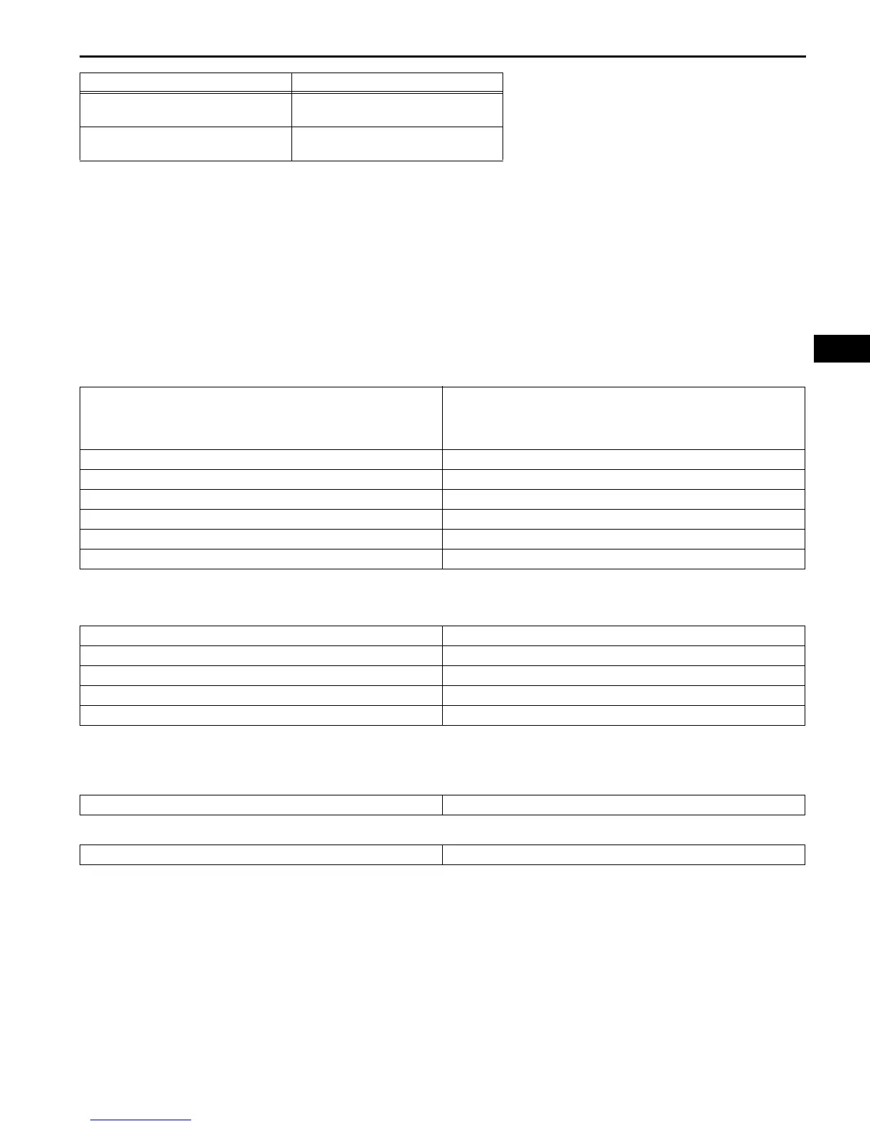
MONITOR STRATEGY
TYPICAL ENABLING CONDITIONS
TYPICAL MALFUNCTION THRESHOLDS
Knock Sensor Range Check (Low voltage) P0327 and P0332:
Knock Sensor Range Check (High voltage) P0328 and P0333:
Equipment Settings
0.01 to 10 V/DIV.
0.01 to 10 ms./DIV.
Conditions
Keep engine speed at 4,000 rpm with
warm engine
Related DTCs
P0327: Knock sensor (Bank 1) open/short (Low voltage)
P0328: Knock sensor (Bank 1) open/short (High voltage)
P0332: Knock sensor (Bank 2) open/short (Low voltage)
P0333: Knock sensor (Bank 2) open/short (High voltage)
Required Sensors/Components (Main) Knock sensor (Bank 1 and 2)
Required Sensors/Components (Related) -
Frequency of Operation Continuous
Duration 1 second
MIL Operation Immediate
Sequence of Operation None
Monitor runs whenever following DTCs are not present None
Battery voltage 10.5 V or more
Time after engine start 5 seconds or more
Engine switch ON
Starter OFF
Knock sensor voltage Less than 0.5 V
Knock sensor voltage More than 4.5 V
Item Content
 Loading...