2GR-FE STARTING – SMART KEY SYSTEM
ST–33
ST
DESCRIPTION
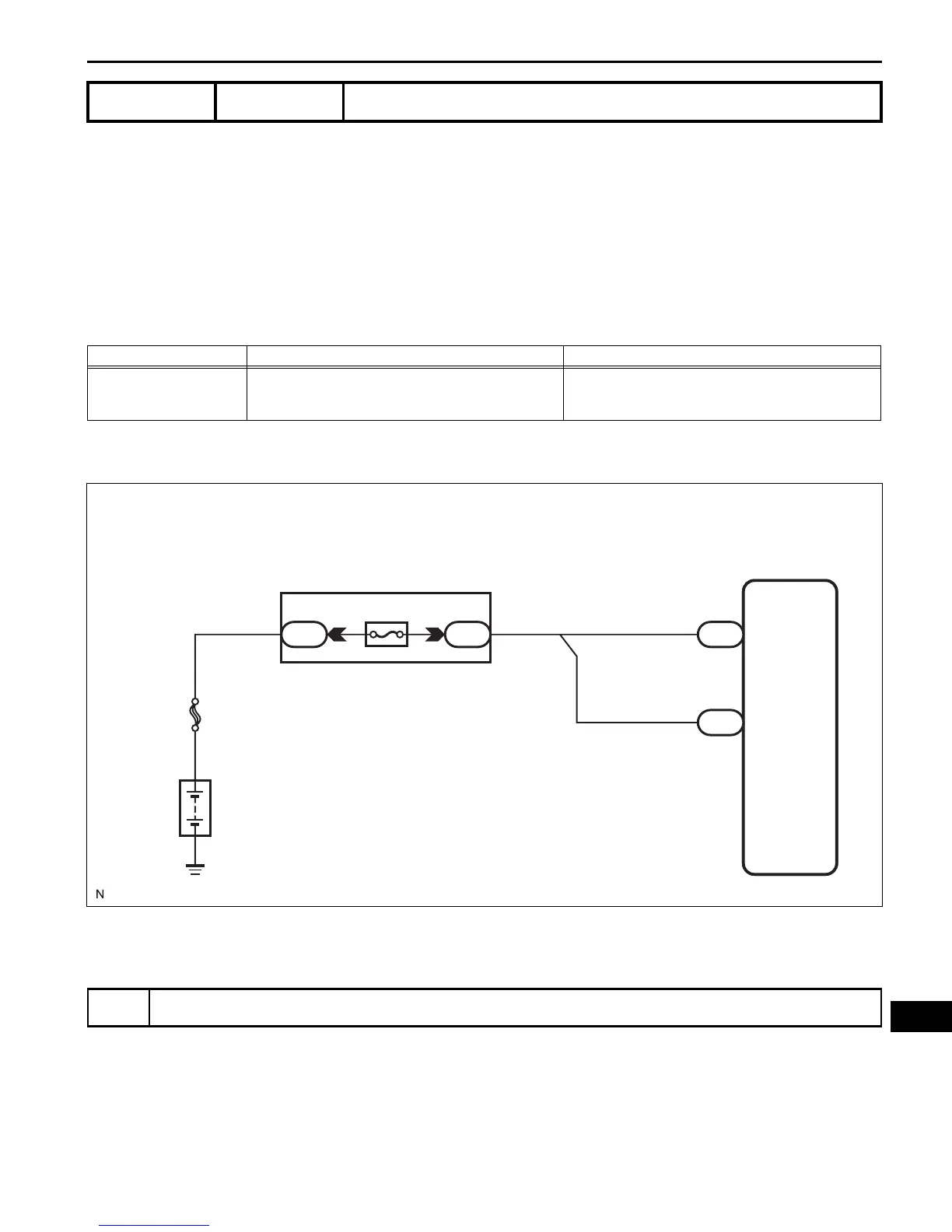
This DTC is output when a problem such as an open in the AM2 fuse, an open or short in the wire harness
between the fuse and main body ECU, a short in the IG output circuit inside the main body ECU, a short
between the main body ECU and relay, and a short in the relay is detected.
HINT:
When the main body ECU is replaced with a new one and the negative (-) battery terminal is connected,
the power source mode becomes the IG-ON mode. When the battery is removed and reinstalled, the
power source mode that was selected when the battery was removed is restored.
After the main body ECU is replaced, perform the registration procedures for the engine immobiliser
system (See page EI-8).
WIRING DIAGRAM
INSPECTION PROCEDURE
(a) Delete the DTCs (See page ST-26).
HINT:
After all DTCs are cleared, check if the trouble occurs
again 6 seconds after the engine switch is turned on
(IG).
(b) Check for DTCs again.
DTC B2271 Ignition Hold Monitor Malfunction
DTC No. DTC Detection Condition Trouble Area
B2271
Hold circuit, IG1 relay actuation circuit or IG2 relay
actuation circuit inside main body ECU is open or
shorted
• AM2 fuse
• Main body ECU
• Wire harness or connector
1
CHECK DTC OUTPUT
Main Body ECU
E7
AM1
AM2
AM2
E6
6
1
1
1
1G
Engine Room J/B and R/B
FL MAIN
Battery
B137971E01
 Loading...