2GR-FE STARTING – SMART KEY SYSTEM
ST–79
ST
DESCRIPTION
This DTC is output when serial communication signals and LIN communication signals in the circuit
between the main body ECU and steering lock actuator (steering lock ECU) are inconsistent.
HINT:
When the main body ECU is replaced with a new one and the negative (-) battery terminal is connected,
the power source mode becomes the IG-ON mode. When the battery is removed and reinstalled, the
power source mode that was selected when the battery was removed is restored.
After the main body ECU or steering lock ECU is replaced, perform the registration procedures for the
engine immobiliser system (See page EI-8).
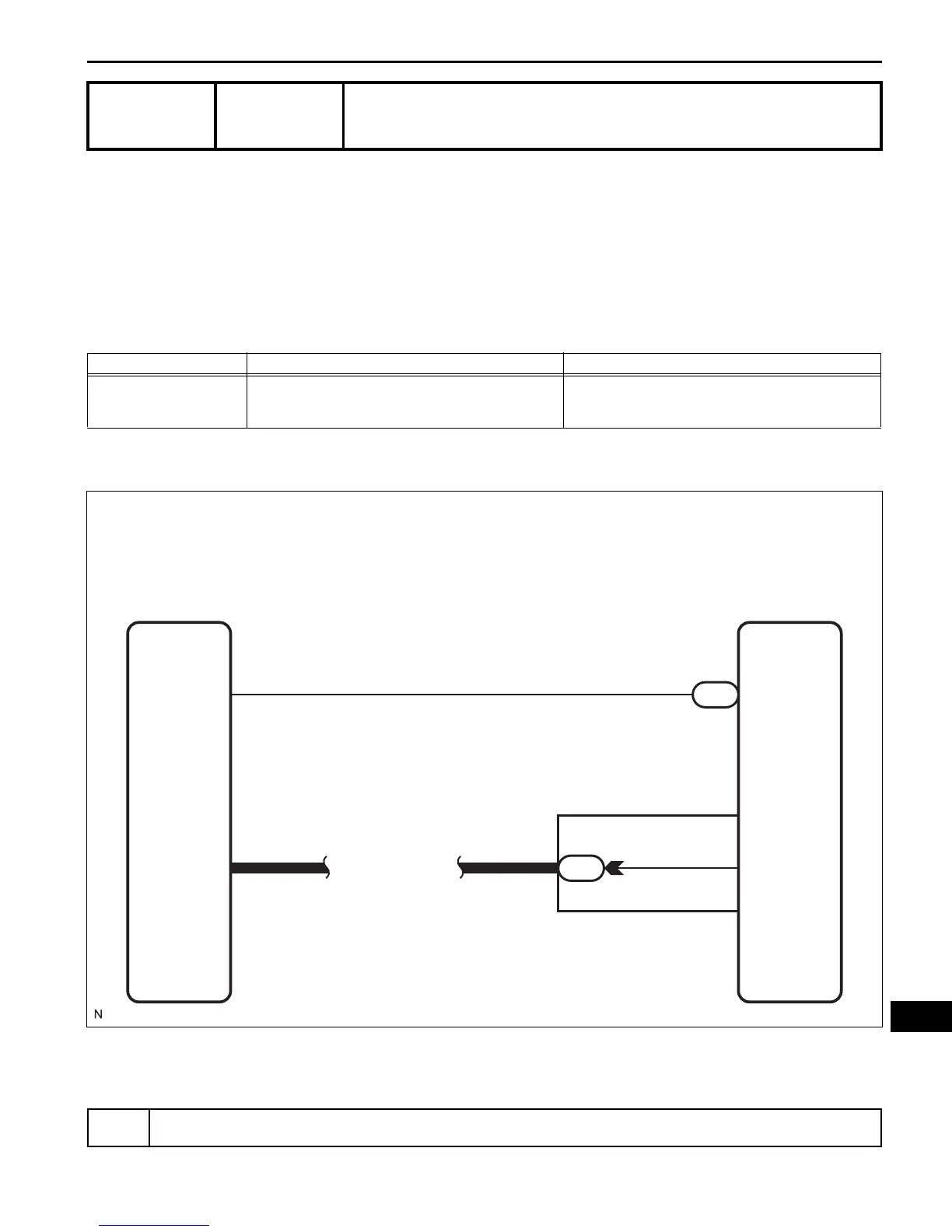
WIRING DIAGRAM
INSPECTION PROCEDURE
(a) Connect the intelligent tester to the DLC3.
DTC B2285
Steering Lock Position Signal Circuit Malfunc-
tion
DTC No. DTC Detection Condition Trouble Area
B2285
Cable and LIN information between the main body ECU
and the steering lock ECU are inconsistent
• Main body ECU
• Steering lock ECU
• Wire harness or connector
1
READ VALUE OF INTELLIGENT TESTER
Main Body ECU
18
14
E7
IR
SLP
SLP1
LIN1
Instrument Panel J/B
LIN Line
LIN
4
9
5
E51
Steering Lock ECU
B137987E01
 Loading...