FU-34
FUEL SYSTEM
-
lniection Pum~
Minus 0" Plus
Idle Speed
A
Maximum Speed
Side
Side
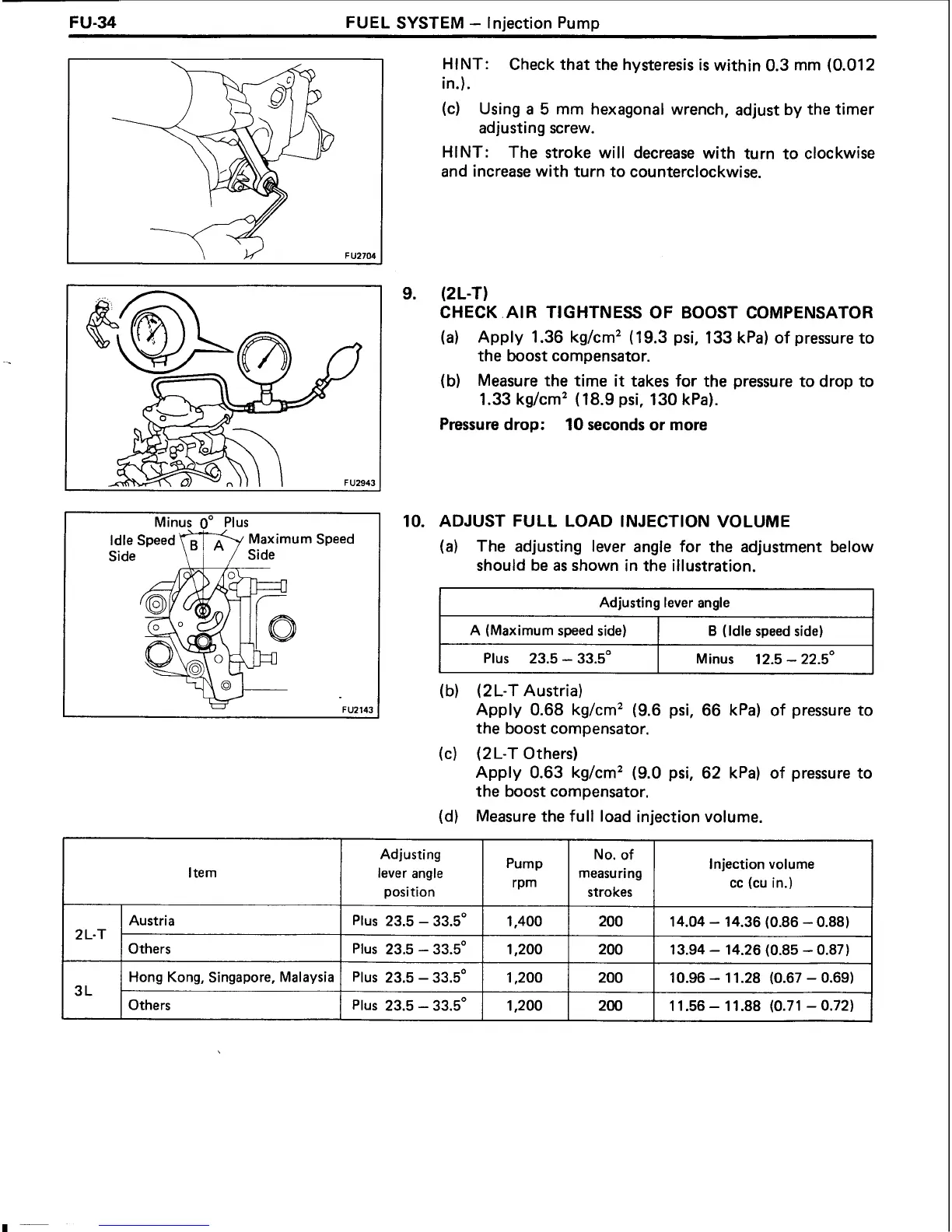
HINT:
Check that the hysteresis
is
within 0.3 mm (0.012
in.).
(c)
Using
a
5
mm hexagonal wrench, adjust by the timer
adjusting screw.
HINT:
The stroke will decrease with turn to clockwise
and increase with turn to counterclockwise.
(2
L-T)
CHECK .AIR TIGHTNESS OF BOOST COMPENSATOR
(a)
Apply 1.36 kg/cm2
(
19.3 psi, 133 kPa) of pressure to
the boost compensator.
(b) Measure the time
it
takes for the pressure to drop to
1.33 kg/cm2
(
18.9 psi, 130 kPa).
Pressure drop:
10
seconds or more
ADJUST FULL LOAD INJECTION VOLUME
(a)
The adjusting lever angle for the adjustment below
should be
as
shown in the illustration.
I
Adjusting lever angle
I
I
A (Maximum speed side)
I
B
(Idle speed side)
I
--
I
Plus 23.5
-
33.5"
I
Minus 12.5
-
22.5"
(b) (2L-T Austria)
Apply 0.68 kg/cm2 (9.6 psi, 66 kPa) of pressure to
the boost compensator.
(c)
(2L-T Others)
Apply 0.63 kg/cm2 (9.0 psi, 62 kPa) of pressure to
the boost compensator.
(d)
Measure the full load injection volume.
Adjusting
lever angle
position
I
2L-T
Pump
rPm
3
L
Austria
Others
No. of
measuring
strokes
Hong Kong, Singapore, Malaysia
Others
Injection volume
cc
(CU in.)
Plus 23.5
-
33.5"
Plus 23.5
-
33.5'
Plus 23.5
-
33.5"
Plus 23.5
-
33.5'
1,400
1.200
1,200
1,200
200
200
- -
14.04
-
14.36 (0.86
-
0.88)
13.94
-
14.26 (0.85
-
0.87)
200
200
10.96
-
11.28 (0.67
-
0.69)
11.56
-
11.88 (0.71
-
0.72)
 Loading...