FU-2
FUEL SYSTEM
-
Fuel Heater System
(LJ)
FUEL
HEATER
SYSTEM
(LJ)
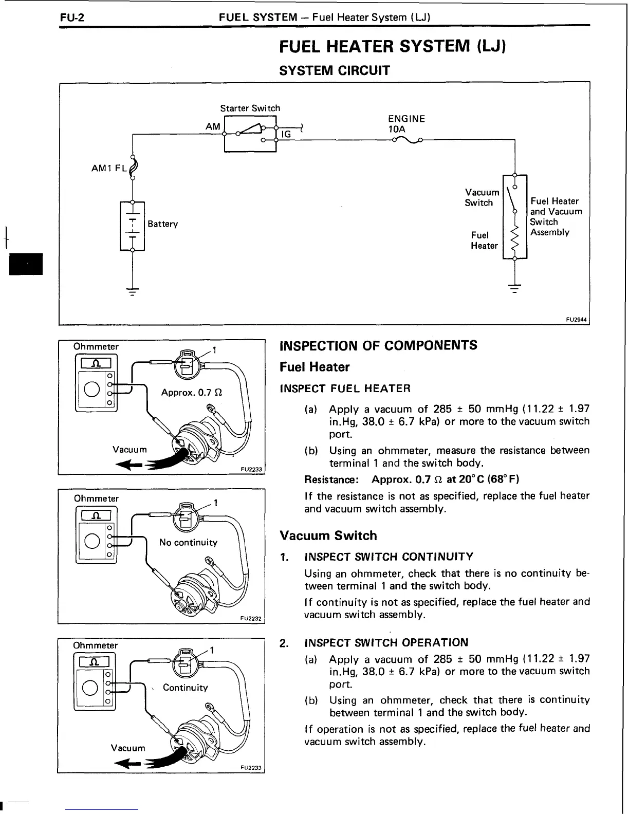
SYSTEM CIRCUIT
Starter Switch
ENGINE
10A
I
Battery
Vacuum
Switch
Fuel
Heater
Fuel Heater
and Vacuum
Switch
Assembly
Ohmmeter
Ohmmeter
\
Continuity
I
I
Vacuum
K
INSPECTION OF COMPONENTS
Fuel Heater
INSPECT FUEL HEATER
(a)
Apply
a
vacuum of 285
t
50 mmHg (1 1.22
It
1.97
in.Hg, 38.0
t
6.7 kPa) or more to the vacuum switch
port.
(b)
Using an ohmmeter, measure the resistance between
terminal 1 and the switch body.
Resistance:
Approx. 0.7
L!
at
20°C
(68"
F)
If the resistance
is
not as specified, replace the fuel heater
and vacuum switch assembly.
Vacuum
Switch
INSPECT SWITCH CONTINUITY
Using an ohmmeter, check that there
is
no continuity be-
tween terminal 1 and the switch body.
If continuity is not as specified, replace the fuel heater and
vacuum switch assembly.
INSPECT SWITCH OPERATION
(a)
Apply a vacuum of 285
r
50 mmHg (1 1.22
?
1.97
in.Hg, 38.0
r
6.7
kPa) or more to the vacuum switch
port.
(b)
Using an ohmmeter, check that there
is
continuity
between terminal 1 and the switch body.
If operation
is
not as specified, replace the fuel heater and
vacuum switch assembly.
 Loading...