EM-48
ENGINE MECHANICAL
-
Cylinder Block
No.
2
and Oil Rings
essed
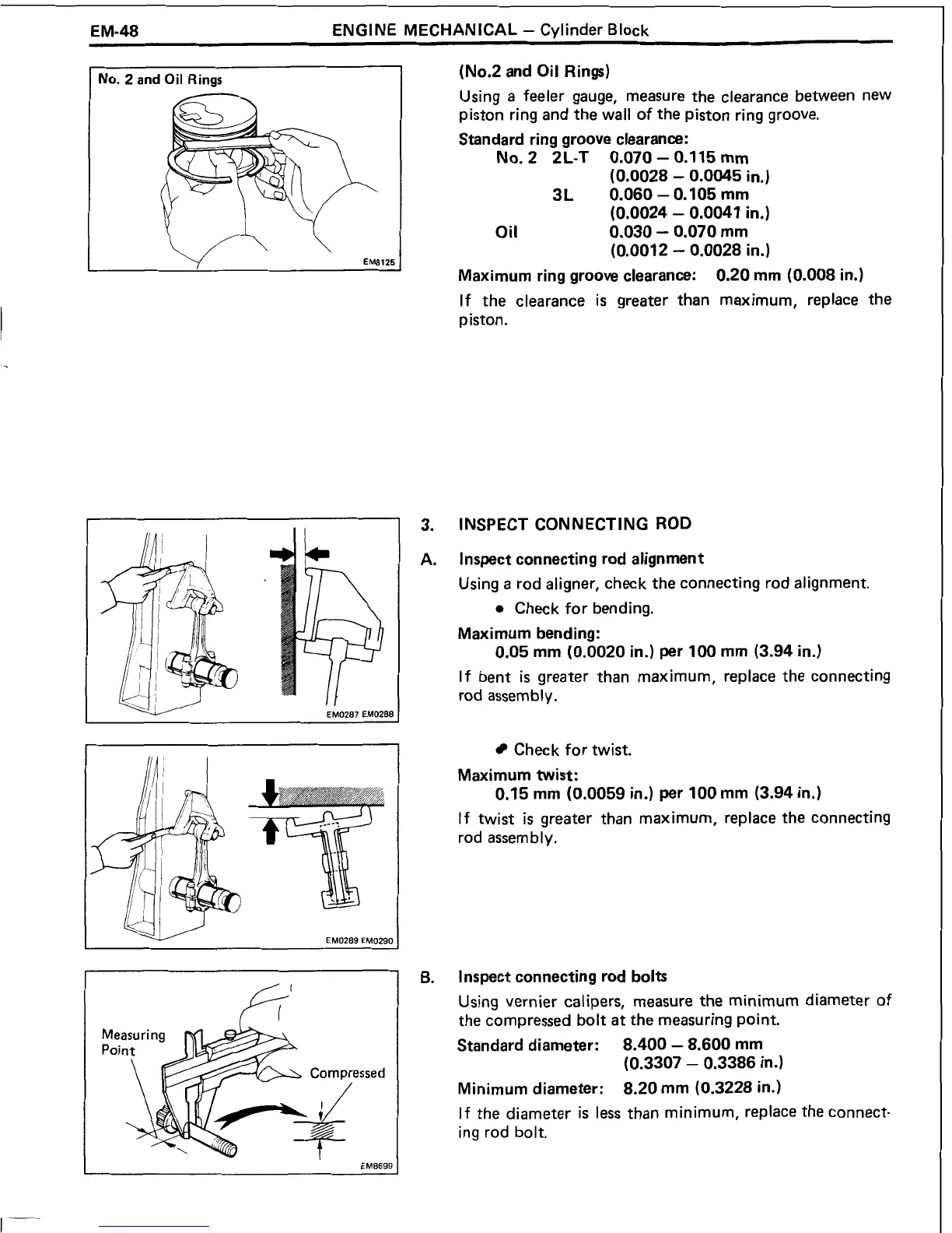
(No.2
and Oil Rings)
Using
a
feeler gauge, measure the clearance between new
piston ring and the wall of the piston ring groove.
Standard ring groove clearance:
No.
2 2L-T 0.070
-
0.1 15
mm
(0.0028
-
0.0045
in.)
3L 0.060
-
0.105
mm
(0.0024
-
0.0041
in.)
Oil
0.030
-
0.070
mm
(0.0012
-
0.0028
in.)
Maximum ring groove clearance:
0.20
mm
(0.008
in.)
If the clearance
is
greater than maximum, replace the
piston.
INSPECT CONNECTING ROD
Inspect connecting rod alignment
Using
a
rod aligner, check the connecting rod alignment.
0
Check for bending.
Maximum bending:
0.05
mm
(0.0020
in.) per
100
mm
(3.94
in.)
If bent
is
greater than maximum, replace the connecting
rod assembly.
Check for twist.
Maximum twist:
0.15
mm
(0.0059
in.) per
100
mm
(3.94
in.)
If twist
is
greater than maximum, replace the connecting
rod assembly.
l
nspect connecting rod bolts
Using vernier calipers, measure the minimum diameter of
the compressed bolt
at
the measuring point.
Standard diameter:
8.400
-
8.600
mm
(0.3307
-
0.3386
in.)
Minimum diameter:
8.20
mm
(0.3228
in.)
If the diameter
is
less than minimum, replace the connect-
ing rod bolt.
 Loading...