9
FUEL SYSTEM/ENGINE MANAGEMENT
INLET AIR TEMPERATURE SENSOR
Fault Code
Possible cause
Action
Polio
Inlet air temperature system fault
View &
note diagnostic tool `freeze frame'
data if available.
View & note diagnostic tool `sensor' data.
Ensure sensor connector is secure.
Disconnect ECM and proceed to pinpoint
test 1:-
P0113
Open circuit, or short circuit to battery+
P0112
Short circuit to earth
disconnect sensor and proceed to pinpoint
test 6
Pinpoint Tests
Test
Result
Action
1
Check cable and terminal integrity:
— ECM pin 34
— ECM pin 11
OK
Proceed to test 2
Faulty
Rectify fault, proceed to test 7
2
Check resistance value:
— ECM pin 11 to ECM pin 34
(Temperature dependent — see data
below)
OK
Disconnect temp sensor and proceed to
test 6
Open circuit
Proceed to test 3
Short circuit
Disconnect temp sensor and proceed to
test 4
3
Check cable continuity:
— ECM pin 11 to sensor pin 1
— ECM pin 34 to sensor pin 2
OK
Proceed to test 5
Open circuit
S
Locate and rectify wiring fault, proceed to
test 7
4
Check cable for short circuit:
— ECM pin 11 to ECM pin 34
OK
Proceed to test 5
Short circuit
Locate and rectify wiring fault, proceed to
test 7
5
Check sensor resistance:
— Sensor pin 1 to sensor pin 2
(Temperature dependent — see data
below)
OK
Proceed to test 7
Faulty
Renew temp sensor, proceed to test 7
6
Check cable for short circuit:
— ECM pin 11 to earth
OK
Proceed to test.7
Short circuit
Locate and rectify wiring fault, proceed to
test 7
7
Reconnect harness, clear fault code and
run engine to verify fault cleared
OK
Action complete — quit test
Fault
Contact Triumph service
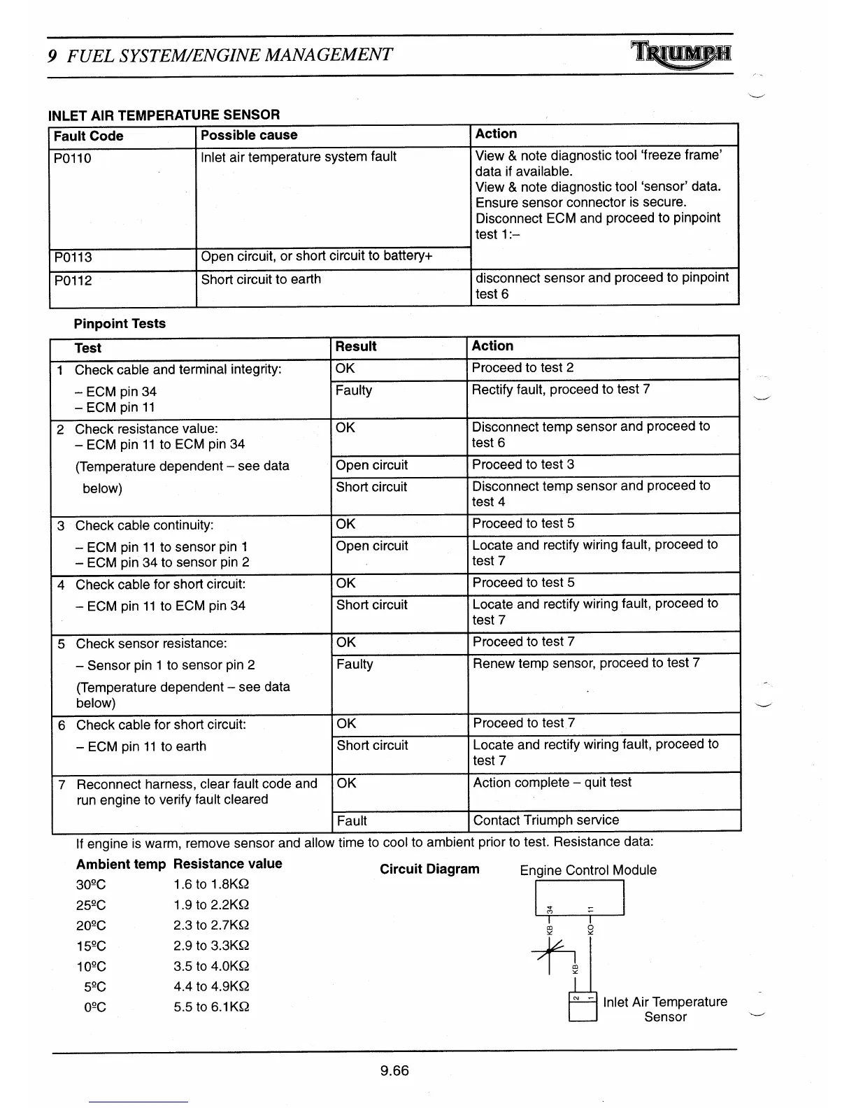
If engine is warm, remove sensor and allow time to cool to ambient prior to test. Hesistance aata:
Ambient temp Resistance value
Circuit Diagram
Engine Control Module
30°C
1.6 to 1.8KQ
25°C
1.9 to 2.2KQ
"
20°C
2.3 to 2.7KQ
m
o
Y
Y
15°C
2.9 to 3.3KQ
10°C
3.5 to 4.OKQ
m
5°C
4.4 to 4.9KQ
0°C
5.5 to 6.1 KQ
Inlet Air Temperature
L
J
Sensor
9.66

 Loading...