9 FUEL SYSTEM/ENGINE MANAGEMENT
T1
UM1I
NOTE:
•
On models with the idle air control valve as
shown in the diagram below, it is not necessary
to disconnect the air bypass hoses when
removing the throttle bodies.
Later Model Air Bypass System
4.
Disconnect the multi-plug leading to the throttle
position sensor.
gala
1.
Throttle Position Sensor
2.
Multi-plug
5.
Release the throttle cable adjusters and
disconnect the throttle cable.
6.
Release any cable ties securing the injector
cables to the fuel rail.
7.
Disconnect the multi-plugs to each injector.
8.
Disconnect the multiplug to the idle air control
valve.
gahz
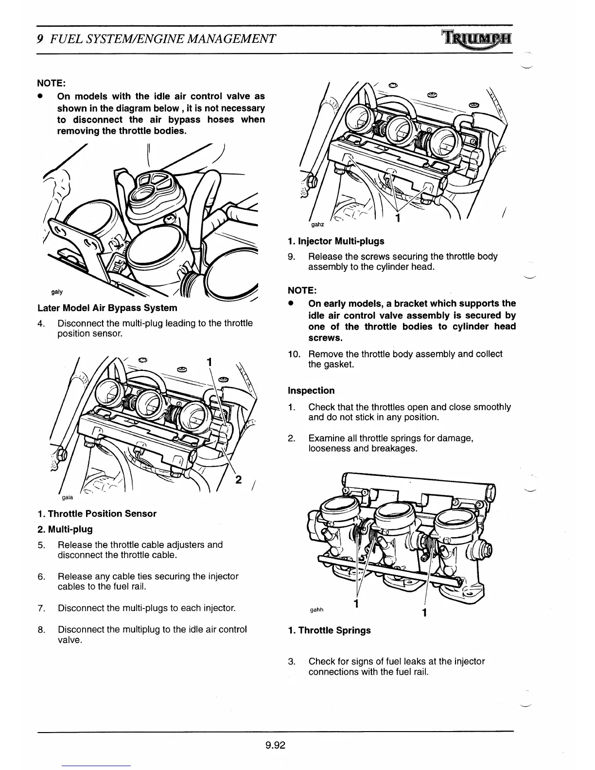
1. Injector Multi-plugs
9.
Release the screws securing the throttle body
assembly to the cylinder head.
NOTE:
•
On early models, a bracket which supports the
idle air control valve assembly is secured by
one of the throttle bodies to cylinder head
screws.
10.
Remove the throttle body assembly and collect
the gasket.
Inspection
1.
Check that the throttles open and close smoothly
and do not stick in any position.
2.
Examine all throttle springs for damage,
looseness and breakages.
gahh
•
1
1. Throttle Springs
3.
Check for signs of fuel leaks at the injector
connections with the fuel rail.
9.92

 Loading...