TRANSMISSION 7
SELECTORS, SELECTOR SHAFT & DRUM
Removal
NOTE:
•
In order to remove the selector mechanism, the
engine must first be removed from the frame
and the two halves of the crankcase separated.
1.
Remove both the input and output shafts.
2.
Remove the capscrew and take out the 'U' shaped
keeper plate from the selector shaft.
-
^
e
J
/
^
i^
1
gada
1. Selector Shaft Keeper Plate
NOTE:
•
To ensure that the selector fork positions are
maintained on assembly, mark each fork with
felt pen or similar to denote their relative
positions.
3.
Using finger pressure, push the selector shaft out of
the crankcase in the direction of the keeper plate.
Collect each selector fork from the lower crankcase
as they are released from the selector shaft.
1. Selector Forks
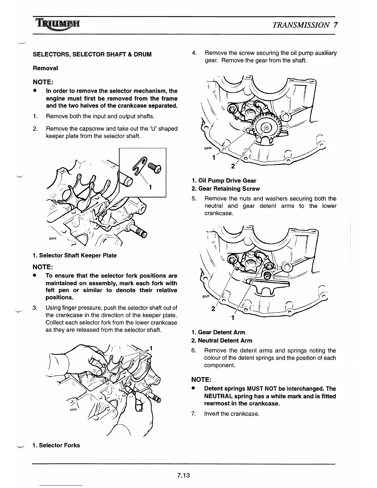
4.
Remove the screw securing the oil pump auxiliary
gear. Remove the gear from the shaft.
2
1.
Oil Pump Drive Gear
2.
Gear Retaining Screw
5.
Remove the nuts and washers securing both the
neutral and gear detent arms to the lower
crankcase.
1.
Gear Detent Arm
2.
Neutral Detent Arm
6.
Remove the detent arms and springs noting the
colour of the detent springs and the position of each
component.
NOTE:
•
Detent springs MUST NOT be interchanged. The
NEUTRAL spring has a white mark and is fi
tt
ed
rearmost in the crankcase.
7.
Invert the crankcase.
7.13

 Loading...