Tke2w
CYLINDER HEAD & CAMSHAFT 3
CYLINDER HEAD DESCRIPTION
All engines are fitted with an aluminium alloy cylinder
head which carries the camshaft, valves and spark
plugs. The -cylinder head is cast as a single entity and
various components are permanently added after
machining.
The camshafts run directly in the head without additional
bearings. Valve clearances are adjusted by changing
variable thickness shims which sit between the valve
tappet and the camshaft. Various different camshaft
profiles are used depending upon engine configuration,
model type and final market destination.
The camshafts are driven by a silent-type chain.
The chain is tensioned by a spring loaded device fitted in
the upper crankcase, and is guided by two rubber blades.
Oil is supplied to the head by an external feed pipe which
is situated at the right hand rear side of the head. Once
supplied to the head, the oil is distributed along internal
drillings within the head casting and camshaft.
Dual valve springs are used to close the inlet and
exhaust valves. These valve springs have close wound
coils at one end to assist in the prevention of valve
bounce at high engine speed and to give a smooth valve
actuation. When assembling the cylinder head it is
important that the close wound, colour coded ends of the
springs are fitted downwards (towards the piston). Both
the tip and seating face of the valves are hardened to
give a long service life.
Due to the methods used to assemble the valve seats
and valve guides to the head, these parts cannot be
replaced.
CAUTION: In any of the following
operations which necessitate the
removal or disconnection of the cam chain,
NEVER turn the engine without the cam chain and
tensioner correctly fitted and adjusted. In the
disassembled condition, the pistons will contact
the valves if the crankshaft is turned, causing
severe engine damage.
CAM COVER
Removal
1.
Remove the seat and disconnect the battery,
negative (black) lead first.
2.
Remove the side panel assembly as detailed in the
body section.
3.
Remove both lower fairings (where fitted).
4.
Remove the fuel tank and airbox as detailed in the
fuel system section.
5.
Disconnect the electrical connections to the ignition
coils, then remove the coils from the cam cover.
1. Coil Connections
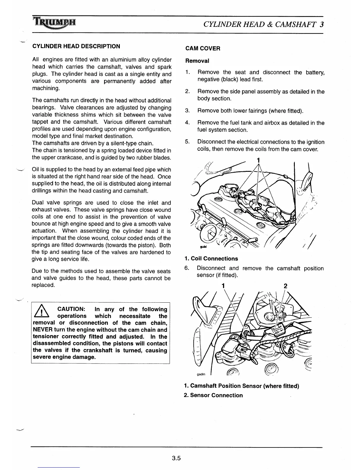
6.
Disconnect and remove the camshaft position
sensor (if fitted).
1
2
1.
Camshaft Position Sensor (where fitted)
2.
Sensor Connection
3.5

 Loading...