Engine Installation
1.
Position the engine beneath the frame.
2.
Raise the engine and loop the drive chain over
the output sprocket.
3.
Align the engine to the frame and refit the engine
mounting bolts to support the engine.
4.
Slacken the inner lock/adjuster rings for the
swinging arm.
5.
Remove the support from beneath the engine.
6.
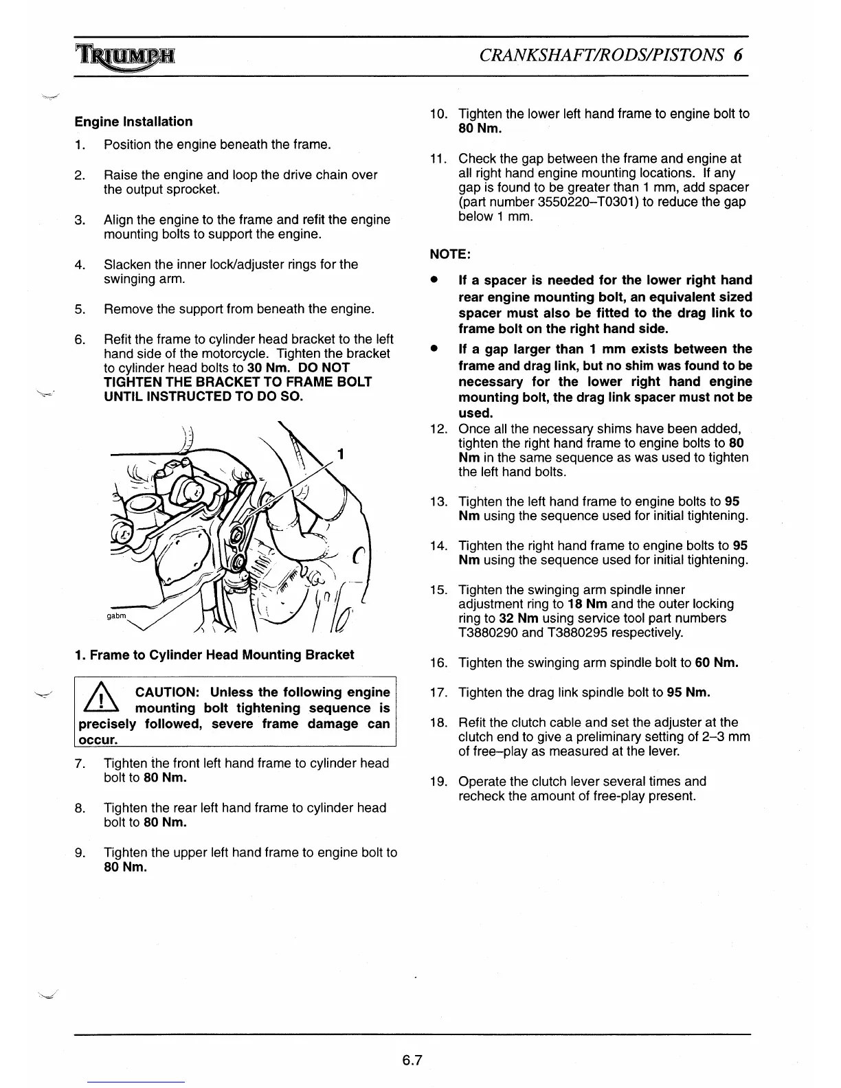
Refit the frame to cylinder head bracket to the left
hand side of the motorcycle. Tighten the bracket
to cylinder head bolts to 30 Nm. DO NOT
TIGHTEN THE BRACKET TO FRAME BOLT
UNTIL INSTRUCTED TO DO SO.
1. Frame to Cylinder Head Mounting Bracket
'
/\
^
CAUTION: Unless the following engine
•
mounting bolt tightening sequence is
precisely followed, severe frame damage can
occur.
7.
Tighten the front left hand frame to cylinder head
bolt to 80 Nm.
8.
Tighten the rear left hand frame to cylinder head
bolt to 80 Nm.
9.
Tighten the upper left hand frame to engine bolt to
80 Nm.
ifl
MPI
CRANKSHAFT/RODS/PISTONS 6
10. Tighten the lower left hand frame to engine bolt to
80 Nm.
11. Check the gap between the frame and engine at
all right hand engine mounting locations. If any
gap is found to be greater than 1 mm, add spacer
(part number 3550220—T0301) to reduce the gap
below 1 mm.
NOTE:
•
If a spacer is needed for the lower right hand
rear engine mounting bolt, an equivalent sized
spacer must also be fitted to the drag link to
frame bolt on the right hand side.
If a gap larger than 1 mm exists between the
frame and drag link, but no shim was found to be
necessary for the lower right hand engine
mounting bolt, the drag link spacer must not be
used.
12.
Once all the necessa
ry
shims have been added,
tighten the right hand frame to engine bolts to 80
Nm in the same sequence as was used to tighten
the left hand bolts.
13. Tighten the left hand frame to engine bolts to 95
Nm using the sequence used for initial tightening.
14. Tighten the right hand frame to engine bolts to 95
Nm using the sequence used for initial tightening.
15. Tighten the swinging arm spindle inner
adjustment ring to 18 Nm and the outer locking
ring to 32 Nm using service tool part numbers
T3880290 and T3880295 respectively.
16.
Tighten the swinging arm spindle bolt to 60 Nm.
17.
Tighten the drag link spindle bolt to 95 Nm.
18.
Refit the clutch cable and set the adjuster at the
clutch end to give a preliminary setting of 2-3 mm
of free—play as measured at the lever.
19.
Operate the clutch lever several times and
recheck the amount of free-play present.
6.7

 Loading...