FUEL SYSTEM/ENGINE MANAGEMENT 9
5.
Drain the engine oil as described in the lubrication
section.
6.
Remove the clutch cover.
7.
Release the sensor multiplug and detach the
sensor grommet from the crankcase.
8.
Release the sensor screws and detach the sensor.
4
1
3
5
3
gact
p
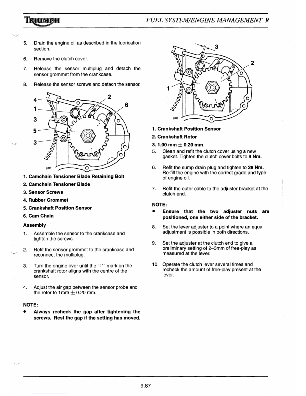
1.
Camchain Tensioner Blade Retaining Bolt
2.
Camchain Tensioner Blade
3.
Sensor Screws
4.
Rubber Grommet
5.
Crankshaft Position Sensor
6.
Cam Chain
Assembly
1.
Assemble the sensor to the crankcase and
tighten the screws.
2.
Refit the sensor grommet to the crankcase and
reconnect the multiplug.
3.
Turn the engine over until the 'Ti' mark on the
crankshaft rotor aligns with the centre of the
sensor.
4.
Adjust the air gap between the sensor probe and
the rotor to 1 mm ± 0.20 mm.
NOTE:
•
Always recheck the gap after tightening the
screws. Rest the gap if the setting has moved.
1
1.
Crankshaft Position Sensor
2.
Crankshaft Rotor
3.
1.00 mm
+
0.20 mm
5.
Clean and refit the clutch cover using a new
gasket. Tighten the clutch cover bolts to
9 Nm.
6.
Refit the sump drain plug and tighten to
28 Nm.
Re-fill the engine with the correct grade and type
of engine oil.
7.
Refit the outer cable to the adjuster bracket at the
clutch end.
NOTE:
•
Ensure that the two adjuster nuts are
positioned, one either side of the bracket.
8.
Set the lever adjuster to a point where an equal
adjustment is possible in both directions.
9.
Set the adjuster at the clutch end to give a
preliminary setting .of 2-3mm of free-play as
measured at the lever.
10.
Operate the clutch lever several times and
recheck the amount of free-play present at the
lever.
9.87

 Loading...