16 ELECTRICAL SYSTEM
i ° 1^U^
1
M1
INSTRUMENTS
Removal
1.
Remove the seat and disconnect the batte
ry
,
negative (black) lead first.
2.
Remove the cockpit fairing (where fitted) as
described in the 'Body' section.
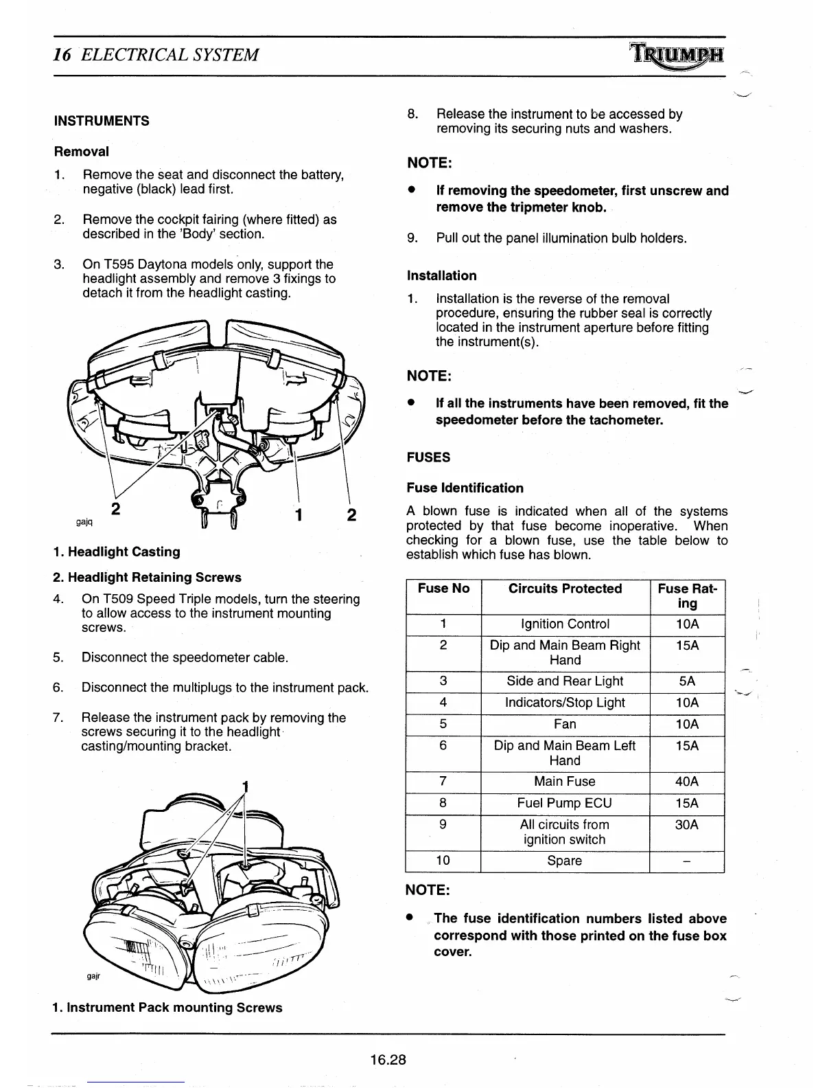
3.
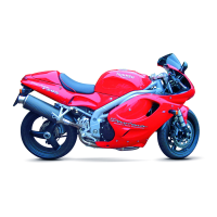
On T595 Daytona models only, support the
headlight assembly and remove 3 fixings to
detach it from the headlight casting.
1.
Headlight Casting
2.
Headlight Retaining Screws
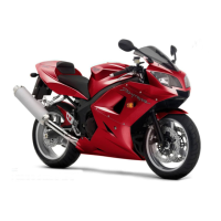
4.
On 1509 Speed Triple models, turn the steering
to allow access to the instrument mounting
screws.
5.
Disconnect the speedometer cable.
6.
Disconnect the multiplugs to the instrument pack.
7.
Release the instrument pack by removing the
screws securing it to the headlight
casting/mounting bracket.
1. Instrument Pack mounting Screws
8.
Release the instrument to be accessed by
removing its securing nuts and washers.
NOTE:
•
If removing the speedometer, first unscrew and
remove the tripmeter knob.
9.
Pull out the panel illumination bulb holders.
Installation
1.
Installation is the reverse of the removal
procedure, ensuring the rubber seal is correctly
located in the instrument aperture before fitting
the instrument(s).
NOTE:
•
If all the instruments have been removed, fit the
speedometer before the tachometer.
FUSES
Fuse Identification
A blown fuse is indicated when all of the systems
protected by that fuse become inoperative. When
checking for a blown fuse, use the table below to
establish which fuse has blown.
Fuse No
Circuits Protected
Fuse Rat-
ing
1
Ignition Control
1 OA
2
Dip and Main Beam Right
Hand
15A
3
Side and Rear Light
5A
4
Indicators/Stop Light
1OA
5
Fan
1OA
6
Dip and Main Beam Left
Hand
15A
7
Main Fuse
40A
8
Fuel Pump ECU
15A
9
All circuits from
ignition switch
30A
10
Spare
—
NOTE:
•
The fuse identification numbers listed above
correspond with those printed on the fuse box
cover.
Aye
16.28

 Loading...