CYLINDER HEAD & CAMSHAFT 3
O4Q1
2
gaaa
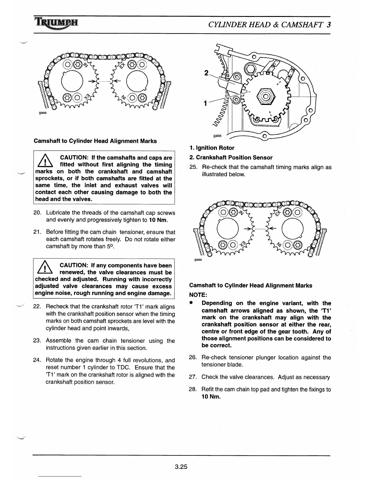
Camsha
ft
to Cylinder Head Alignment Marks
A
CAUTION: If the camshafts and caps are
fi
tt
ed without first aligning the timing
marks on both the crankshaft and camshaft
sprockets, or if both camshafts are fi
tt
ed at the
same time, the inlet and exhaust valves will
contact each other causing damage to both the
head and the valves.
20.
Lubricate the threads of the camshaft cap screws
and evenly and progressively tighten to 10 Nm.
21.
Before fitting the cam chain tensioner, ensure that
each camshaft rotates freely. Do not rotate either
camshaft by more than 5°.
1.
Ignition Rotor
2.
Crankshaft Position Sensor
25. Re-check that the camshaft timing marks align as
ill
ustrated below.
o4Q
gaaa
^
CAUTION: If any components have been
•
renewed, the valve clearances must be
checked and adjusted. Running with incorrectly
adjusted valve clearances may cause excess
engine noise, rough running and engine damage.
22.
Recheck that the crankshaft rotor
'Ti'
mark aligns
with the crankshaft position sensor when the timing
marks on both camshaft sprockets are level with the
cylinder head and point inwards,
23.
Assemble the cam chain tensioner using the
instructions given earlier in this section.
24.
Rotate the engine through 4 full revolutions, and
reset number 1 cylinder to TDC. Ensure that the
'Ti'
mark on the crankshaft rotor is aligned with the
crankshaft position sensor.
Camshaft to Cylinder Head Alignment Marks
NOTE:
•
Depending on the engine variant, with the
camshaft arrows aligned as shown, the
'Ti'
mark on the crankshaft may align with the
crankshaft position sensor at either the rear,
centre or front edge of the gear tooth. Any of
those alignment positions can be considered to
be correct.
26.
Re-check tensioner plunger location against the
tensioner blade.
27.
Check the valve clearances. Adjust as necessa
ry
28.
Refit the cam chain top pad and tighten the fixings to
10 Nm.
3.25

 Loading...