6 CRANKSHAFT/RODS/PISTONS
T
MPH
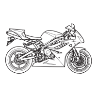
3.
Apply silicone sealer to the liner to crankcase
mating face.
1.
Liner
2.
Sealer Area
4.
Fit the piston and connecting rod assembly into
the liner.
5.
Fit the liner into the crankcase ensuring that the
arrow on the piston faces forward, and the oil hole
in the connecting rod faces rearward.
NOTE:
•
Ensure that the piston/liner/connecting rod
assembly aligns correctly with the crankpin
during assembly into the crankcase.
1.
Crankpin
2.
Big End
6.
Select big end bearing shells using the selection
process elsewhere in this section.
7.
Lubricate both surfaces of the bearing shells with
engine oil and fit to the connecting rod and big
end cap.
8.
Align the connecting rod to the crankshaft and fit
the big end cap. Tighten the cap (using new nuts
and bolts) as follows:
Lubricate the threads of the bolt and the face of
the nut with molybdenum disulphide grease.
Tighten the nuts progressively in 2 stages;—
CAUTION: The torque characteristics of
•
the connecting rod nuts and bolts are
sensitive to the rate at which they are tightened. If
all the torque is applied in one action, the bolt may
be stretched and the nut may become loose when
in service resulting in an expensive engine failure.
firstly to 14 Nm
then through 120
0
of nut rotation as measured
using the Triumph torque turn gauge
3880105-T0301.
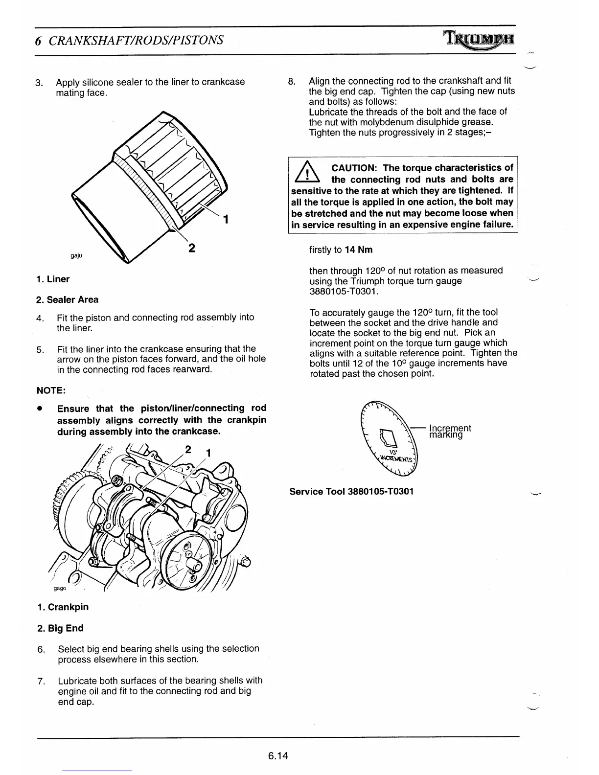
To accurately gauge the 120° turn, fit the tool
between the socket and the drive handle and
locate the socket to the big end nut. Pick an
increment point on the torque turn gauge which
aligns with a suitable reference point. Tighten the
bolts until 12 of the 10° gauge increments have
rotated past the chosen point.
Increment
marKing
^'^C.Ri^1ENZS
Service Tool 3880105-T0301
6.14

 Loading...