60C5D11
5-8
1
2
3
4
5
6
7
8
9
10. Measure the valve pad thickness with a
micrometer.
Select the necessary valve pad by calcu-
lating its thickness with the following for-
mula.
Example:
If the “Removed valve pad thickness” is 2.10
mm, the “Checked valve clearance” is 0.30
mm and the “Specified valve clearance” is
0.20 mm, then the necessary valve pad thick-
ness = 2.10 + 0.30 – 0.20 = 2.20 mm
11. Install the necessary valve pad into the
valve lifter.
12. Install the camshafts, camshaft caps,
driven sprockets, and timing belt, and
then tighten the tensioner bolt.
13. Check the valve clearance. Adjust if nec-
essary.
14. Loosen the tensioner bolt, and then
remove the timing belt and driven sprock-
ets.
15. Install the cylinder head cover and driven
sprockets.
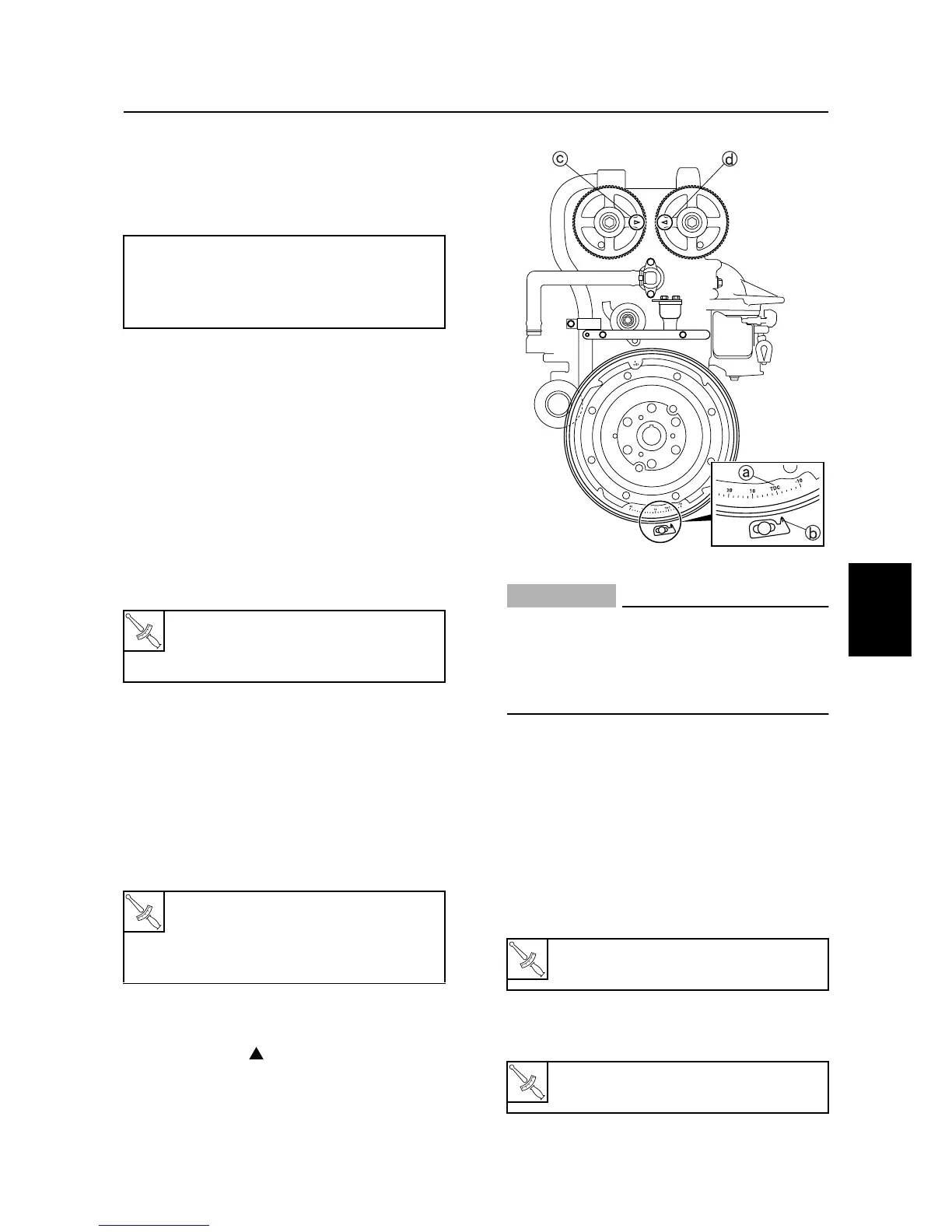
16. Check that the TDC mark
a
on the fly-
wheel magnet is aligned with the pointer
b
, and that “” marks
c
and
d
on the
driven sprockets are aligned. Adjust if
necessary.
CAUTION:
• Do not turn the flywheel magnet coun-
terclockwise, otherwise the valve sys-
tem may be damaged.
• Do not remove the ignition timing
pointer.
17. Install the timing belt, and then tighten
the tensioner bolt finger tight.
18. Turn the flywheel magnet clockwise two
turns, and then check that the alignment
marks are aligned.
19. Tighten the tensioner bolt to the specified
torque.
20. Install the spark plugs, and then connect
the high-tension cords and fuel hoses.
Necessary valve pad thickness =
Removed valve pad thickness + Measured
valve clearance – Specified valve
clearance
T
R
.
.
Camshaft cap bolt:
1st: 8 N·m (0.8 kgf·m, 5.8 ft·lb)
2nd: 17 N·m (1.7 kgf·m, 12 ft·lb)
T
R
.
.
Cylinder head cover:
8 N·m (0.8 kgf·m, 5.8 ft·lb)
Driven sprocket:
60 N·m (6.0 kgf·m, 43 ft·lb)

 Loading...