60C5D11
8-10
1
2
3
4
5
6
7
8
9
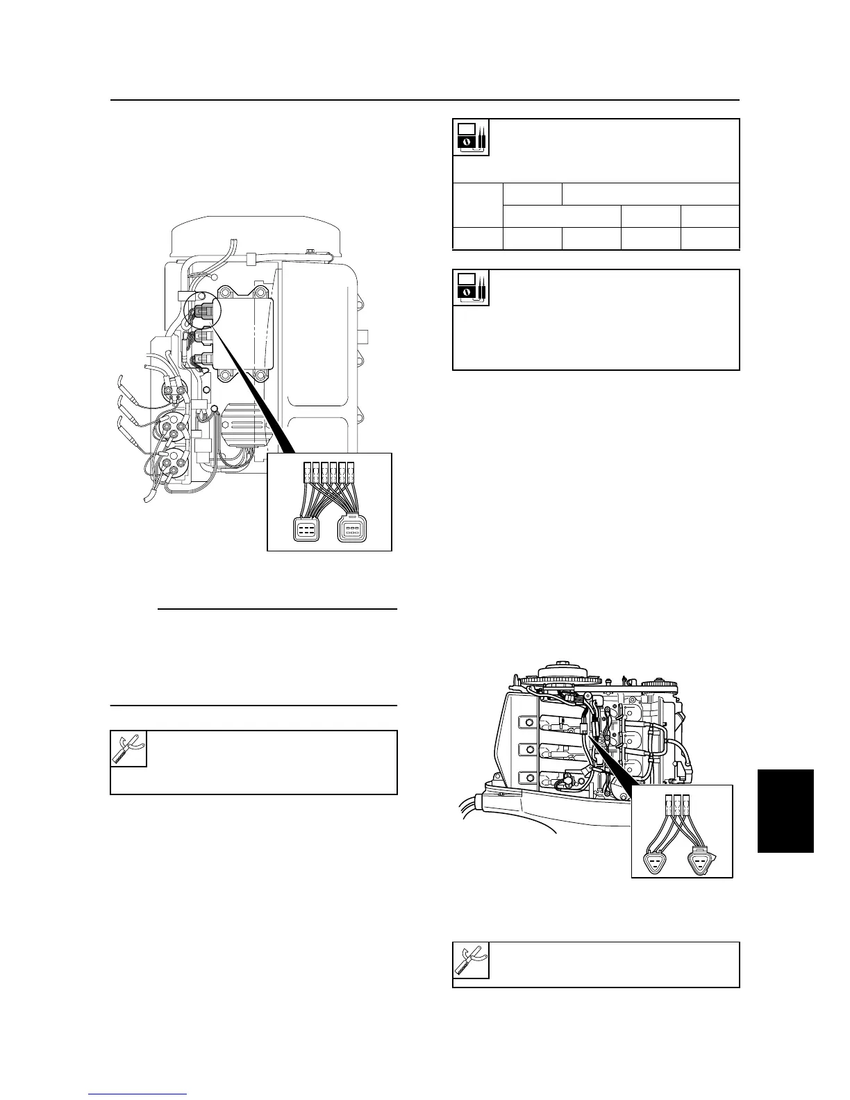
Checking the pulser coil
1. Measure the pulser coil output peak volt-
age. Replace the pulser coil if below
specification.
NOTE:
• Use the peak voltage adaptor with the digi-
tal circuit tester.
• When measuring the peak voltage, set the
selector on the digital circuit tester to the
DC voltage mode
.
Checking the throttle position
sensor
1. Start the engine and warm it up 5 min-
utes to check the stability of the engine.
2. Measure the throttle position sensor
input voltage. Replace the CDI unit if out
of specification.
3. Measure the throttle position sensor out-
put voltage. Replace the CDI unit if out of
specification.
Digital circuit tester: 90890-03174
Peak voltage adaptor: 90890-03172
Test harness (6 pins): 90890-06772
S60C8140
Pulser coil output peak voltage:
White/red (W/R) – Black (B)
White/black (W/B) – Black (B)
r/min
Unloaded
Loaded
Cranking 1,500 3,500
DC V 3.5 2.5 9.0 14.0
Pulser coil resistance (use as
reference):
White/red (W/R) – Black (B)
White/black (W/B) – Black (B)
445–545
Ω
at 20 °C (68 °F)
Test harness (3 pins): 90890-06757
S60C8160
Ignition system and ignition control system

 Loading...


