60C5D11
4-18
1
2
3
4
5
6
7
8
9
NOTE:
Make sure that there is complete clearance
between the throttle cam roller
4
and the
cam surface.
5. Adjust the length of the throttle link rod
5
, and then tighten the nut
6
securely.
6. Move the throttle control lever
1
to
check that the throttle valve opens and
closes smoothly. Also, check that the
throttle cam roller
4
moves freely to the
fully open position
c
on the throttle cam
3
.
7. Set the throttle to the fully closed position
and check that the fully closed mark
a
aligns with the center of the link lever
b
.
NOTE:
Make sure that there is no interference
between the throttle control lever
1
and the
throttle position sensor lead
7
.
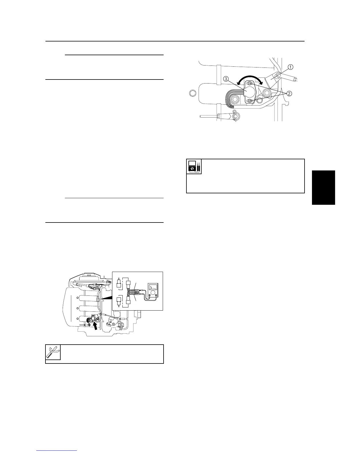
Adjusting the throttle position
sensor
1. Connect the test harness (3 pins) and
digital circuit tester.
2. Start the engine and warm it up for 5 min-
utes to check the stability of the engine.
3. Contact the throttle control lever
1
with
the fully closed stopper.
4. Loosen the screws
2
.
5. Adjust the position of the throttle position
sensor
3
until the specified voltage is
obtained.
6. Tighten the screws
2
.
Digital circuit tester: 90890-03174
Test harness (3 pins): 90890-06757
O
P
S60C4270
Throttle position sensor output
voltage:
Pink (P) – Orange (O)
0.68–0.72 V
S60C4280
Carburetor

 Loading...