60C5D11
1-22
1
2
3
4
5
6
7
8
9
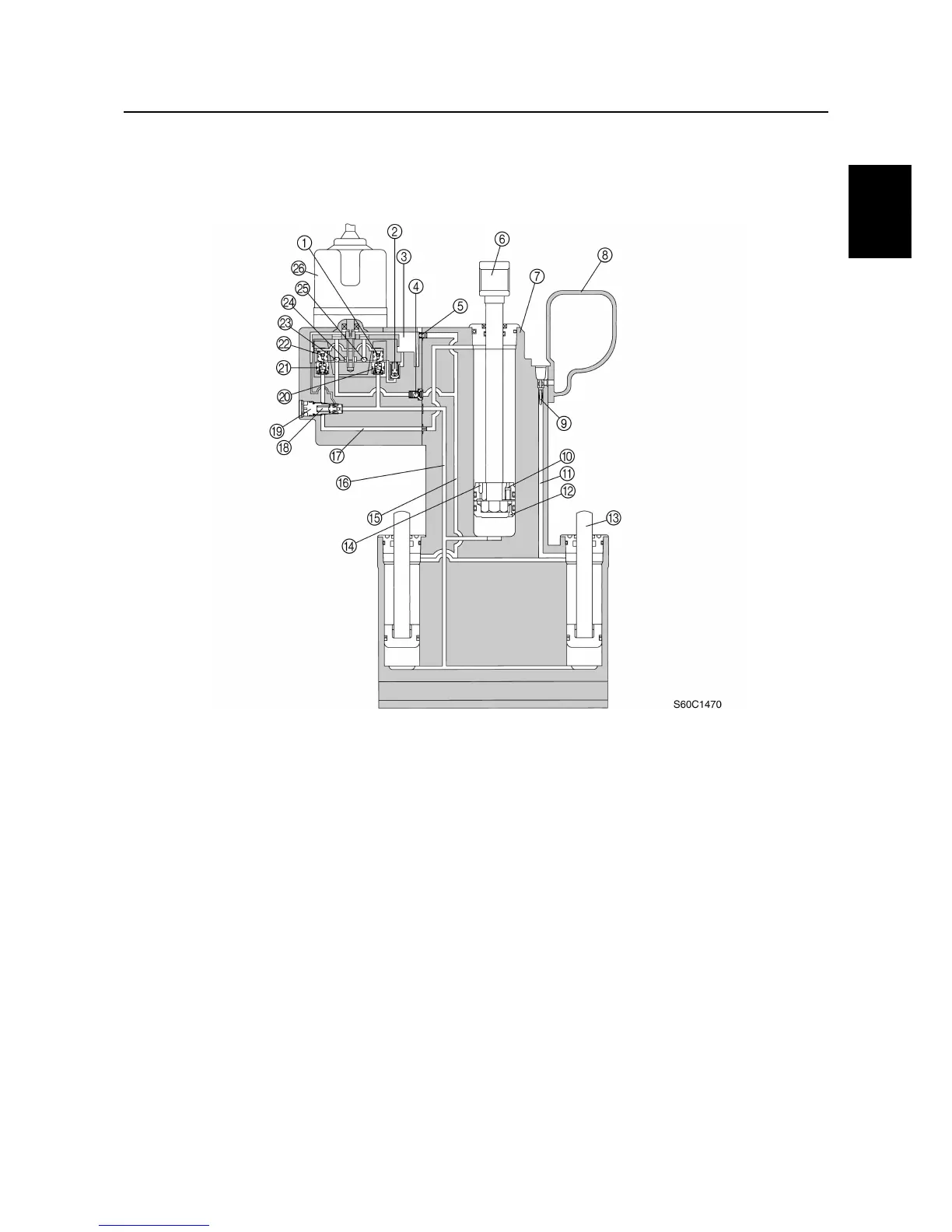
PTT (power trim and tilt) unit (F100B)
The circuit of the PTT unit and the location of its major components are shown in the illustration
below.
1
Lower chamber shuttle valve
2
Up-relief valve
3
Pump chamber
4
Down-check valve
5
Check valve
6
Tilt ram
7
Trim and tilt housing
8
Reservoir
9
Filter screen
0
Shock valve
A
Passage to reservoir
B
Free piston check valve
C
Trim ram
D
Shock return valve
E
Passage to upper chamber of trim cylinders
F
Passage to lower chambers of tilt cylinder and
trim cylinders
G
Passage to upper chamber of tilt cylinder
H
Thermal valve
I
Manual valve
J
Lower chamber check valve
K
Upper chamber check valve
L
Upper chamber shuttle valve
M
Up-intake valve
N
Pump
O
Down-intake valve
P
Motor
Technical tips
 Loading...


