POWR
Power unit
5-31
60C5D11
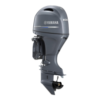
8. If the valve seat contact area is too nar-
row and situated near the bottom edge of
the valve face, use a 60° cutter to cut the
bottom edge of the valve seat. If neces-
sary, use a 45° cutter to center the area
and set its width.
b
Previous contact width
9. Apply a thin, even layer of lapping com-
pound onto the valve seat, and then lap
the valve using a valve lapper (commer-
cially obtainable).
CAUTION:
Do not get the lapping compound on the
valve stem and valve guide.
10. After every lapping procedure, be sure to
clean off any remaining lapping com-
pound from the cylinder head and the
valve.
11. Check the valve seat contact area of the
valve again.
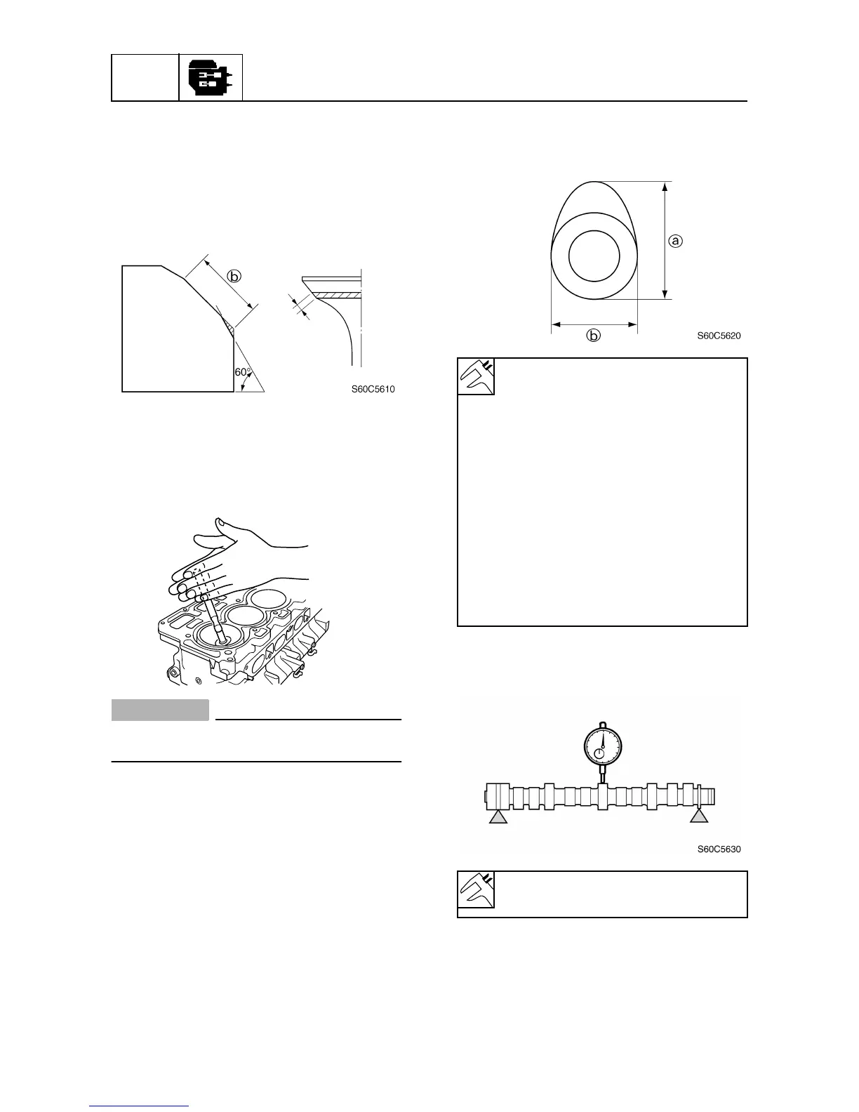
Checking the camshaft
1. Measure the cam lobe. Replace if out of
specification.
2. Measure the camshaft runout. Replace if
out of specification.
S60C5500
Cam lobe
a:
Intake:
37.22–37.38 mm
(1.4654–1.4716 in)
Exhaust:
36.90–37.06 mm
(1.4528–1.4590 in)
Cam lobe b:
Intake:
29.92–30.08 mm
(1.1780–1.1842 in)
Exhaust:
29.92–30.08 mm
(1.1780–1.1842 in)
Camshaft runout limit:
0.1 mm (0.004 in)

 Loading...