60C5D11
6-54
1
2
3
4
5
6
7
8
9
Shimming
NOTE:
• Shimming is not required when assembling
the original lower case and inner parts.
• Shimming is required when assembling the
original inner parts and a new lower case.
• Shimming is required when replacing the
inner part(s).
Selecting the pinion shims
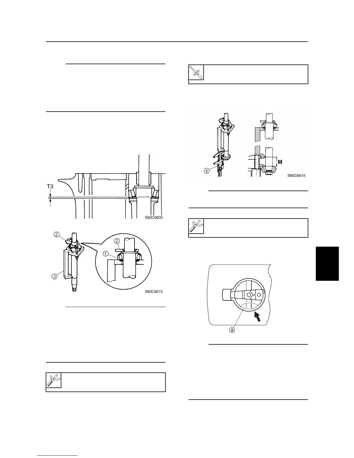
1. Install the drive shaft and drive shaft
bearing
1
to the shimming tools.
NOTE:
• Select the shim thickness (T3) by using the
specified measurement(s) and the calcula-
tion formula.
• Install the shimming tool to the drive shaft
so that the shaft is at the center of the hole.
• Tighten the wing nuts another 1/4 of a turn
after they contact the fixing plate
2
.
2. Install the pinion and pinion nut, and then
tighten the nut to the specified torque.
3. Measure the distance (M) between the
shimming tool and the pinion as shown.
NOTE:
Measure the pinion at three points to find the
clearance average.
4. Calculate the pinion shim thickness (T3)
as shown in the examples below.
NOTE:
“P” is the deviation of the lower case dimen-
sion from standard. The “P” mark
a
is
stamped on the trim tab mounting surface of
the lower case in 0.01 mm units. If the “P”
mark is unreadable, assume that “P” is zero
and check the backlash when the unit is
assembled.
Pinion height gauge
3
:
90890-06702

 Loading...