60C5D11
7-68
1
2
3
4
5
6
7
8
9
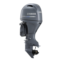
4. Inject grease into both grease nipples
until grease comes out from the bushings
a
.
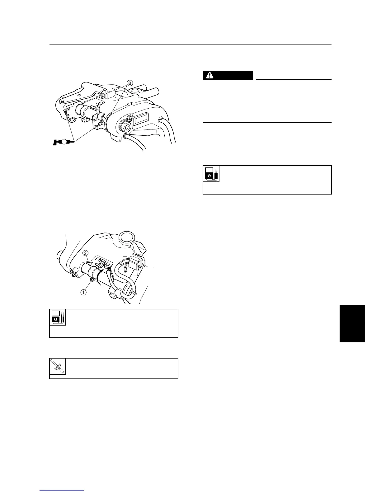
Adjusting the trim sensor cam
1. Fully tilt the outboard motor down.
2. Loosen the screw
1
.
3. Adjust the position of the trim sensor cam
2
until the specified resistance is
obtained.
4. Tighten the screw
1
.
5. Fully tilt the outboard motor up, and then
support it with the tilt stop lever.
WARNING
After tilting up the outboard motor, be
sure to support it with the tilt stop lever.
Otherwise, the outboard motor could sud-
denly lower if the power trim and tilt unit
should lose fluid pressure.
6. Measure the trim sensor resistance.
Check the trim sensor if out of specifica-
tion.
Trim sensor resistance:
Pink (P) – Black (B)
9–11
Ω
at 20 °C (68 °F)
T
R
.
.
Trim sensor cam screw
1
:
2 N·m (0.2 kgf·m, 1.4 ft·lb)
S60C7275
AA
S60C7185
Gy
P
B
Trim sensor resistance:
Pink (P) – Black (B)
238.8–378.8
Ω
at 20 °C (68 °F)
Clamp brackets (F100C)

 Loading...