MP-1xx SIP User’s Manual 2. MP-1xx Physical Description
Version 4.4 23 March 2005
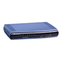
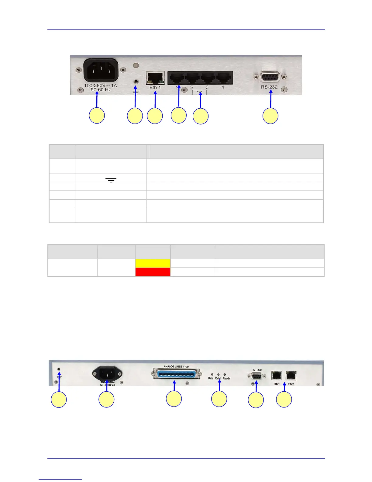
Figure 2-3: MP-104/FXS Rear Panel Connectors
Table 2-3: MP-10x Rear Panel Component Descriptions
Item # Label Component Description
1
100-250V ~ 1A
50-60 Hz
AC power supply socket.
2
Protective earthing screw (mandatory for all installations).
3 Eth 1
10/100 Base-TX Ethernet connection.
4
2, 4 or 8 FXS/FXO ports.
5 FXS
FXS / FXO label.
6 RS-232
9 pin RS-232 status port (for Cable Wiring of the RS-232 refer to Figure
3-10 on page 32).
Table 2-4: Indicator LEDs on the MP-10x Rear Panel
Label Type Color State Meaning
Yellow ON
Ethernet port receiving data
ETH-1
Ethernet Status
Red ON
Collision
Note that the Ethernet LEDs are located within the RJ-45 socket.
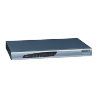
2.2.2 MP-124 Rear Panel
Figure 2-4 illustrates the rear panel layout of the MP-124. For descriptions of the MP-124 rear
panel components, refer to Table
2-5. For the functionality of the MP-124 rear panel LEDs, refer
to Table
2-6.
Figure
2-4: MP-124 (FXS) Rear Panel Connectors
1
2 3
4
6
5
1
2
3
4
6
5
 Loading...