MP-1xx SIP User’s Manual 3. Installing the MP-1xx
Version 4.4 31 March 2005
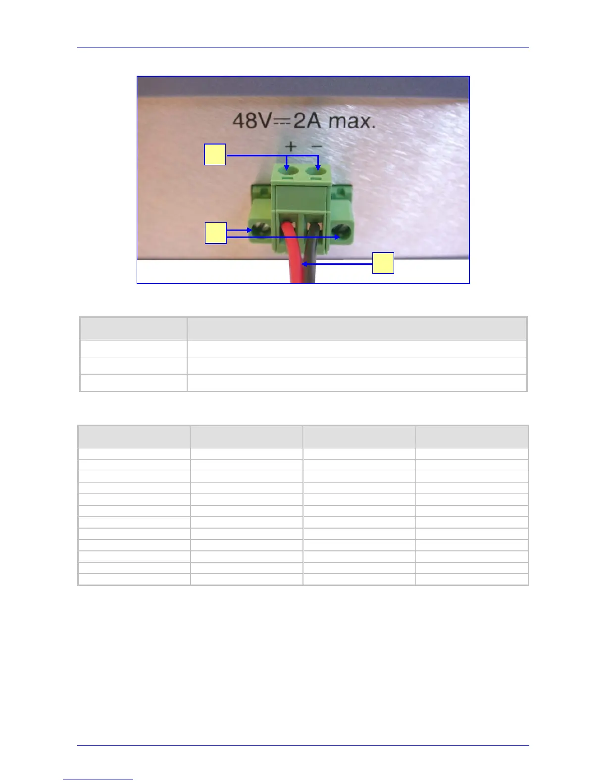
Figure 3-9: DC Power Supply on the MP-124
Table
3-2: DC Power Supply on the MP-124 Component Descriptions
Item #
Component Description
1 2 screws for wire connection to the DC terminal block.
2 2 screws for connecting the DC terminal block to the MP-124 panel.
3 Two 18 AWG wires.
Table 3-3: Pin Allocation in the 50-pin Telco Connector
Phone Channel Connector Pins Phone Channel Connector Pins
1 1/26 13 13/38
2 2/27 14 14/39
3 3/28 15 15/40
4 4/29 16 16/41
5 5/30 17 17/42
6 6/31 18 18/43
7 7/32 19 19/44
8 8/33 20 20/45
9 9/34 21 21/46
10 10/35 22 22/47
11 11/36 23 23/48
12 12/37 24 24/49
1
2
3
 Loading...