MP-1xx SIP User’s Manual 3. Installing the MP-1xx
Version 4.4 25 March 2005
3 Installing the MP-1xx
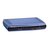
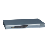
This section provides information on the hardware installation procedure for the MP-1xx. For
information on how to start using the gateway, refer to Section
4 on page 35. For detailed
information on the MP-1xx connectors, LEDs and buttons, refer to Section
2 on page 21.
Caution Electrical Shock
The equipment must only be installed or serviced by qualified service personnel.
To install the MP-1xx, take these 4 steps:
1. Unpack the MP-1xx (refer to Section 3.1 below).
2. Check the package contents (refer to Section
3.2 below).
3. Mount the MP-1xx (refer to Section
3.3 on page 26).
4. Cable the MP-1xx (refer to Section
3.4 on page 29).
After connecting the MP-1xx to the power source, the Ready and LAN LEDs on the front panel
turn to green (after a self-testing period of about 1 minute). Any malfunction changes the Ready
LED to red.
When you have completed the above relevant sections you are then ready to start configuring the
gateway (Section
4 on page 35).
3.1 Unpacking
To unpack the MP-1xx, take these 6 steps:
1. Open the carton and remove packing materials.
2. Remove the MP-1xx gateway from the carton.
3. Check that there is no equipment damage.
4. Check, retain and process any documents.
5. Notify AudioCodes or your local supplier of any damage or discrepancies.
6. Retain any diskettes or CDs.
3.2 Package Contents
Ensure that in addition to the MP-1xx, the package contains:
• AC power cable for the AC power supply option.
• DC terminal block (MP-124 only, for the DC power supply option).
• CD (software and documentation).
• Lifeline cable (RJ-11 adaptor cable for 1 to 2). (Supplied with MP-10x/FXS only).
• 3 brackets (2 short, 1 long) and bracket-to-device screws for 19-inch rack installation option
(MP-10x only).
• 2 short equal-length brackets and bracket-to-device screws for MP-124 19-inch rack
installation.
• The MP-1xx Fast Track Installation Guide.

 Loading...

