MP-1xx SIP User’s Manual 3. Installing the MP-1xx
Version 4.4 29 March 2005
3.4 Cabling the MP-1xx
Verify that you have the cables listed under column ‘Cable’ in Table 3-1 before beginning to cable
the MP-1xx according to the column ‘Cabling Procedure’. For detailed information on the MP-1xx
rear panel connectors, refer to Section
2.2 on page 22.
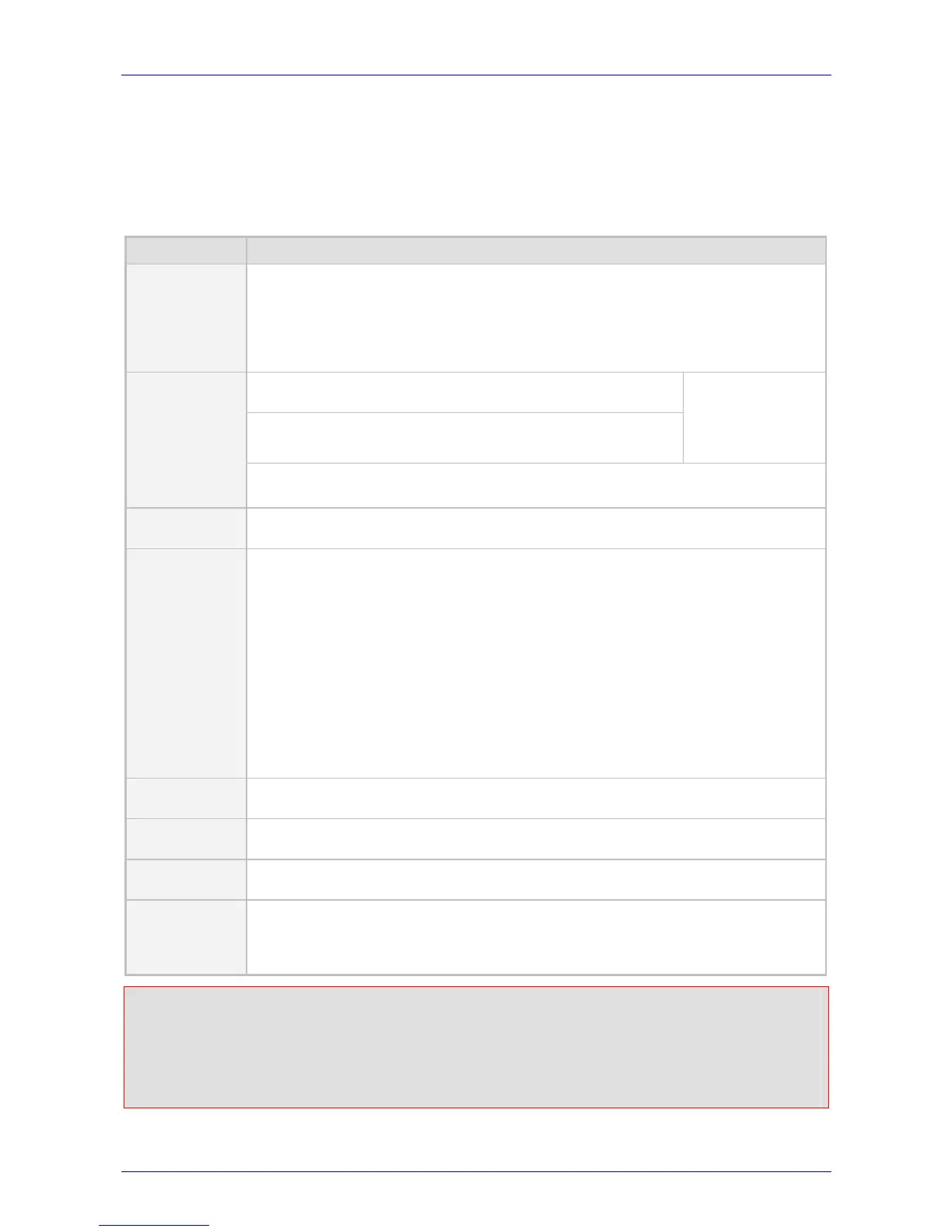
Table
3-1: Cables and Cabling Procedure
Cable Cabling Procedure
RJ-45
Ethernet
cable
When initializing (connecting the MP-1xx to the network for the first time) use a standard
Ethernet cable to connect the network interface on your computer to a port on a network
hub / switch. Use a second standard Ethernet cable to connect the MP-1xx to another
port on the same network hub / switch.
For normal use, connect the MP-1xx Ethernet connection directly to the network, using a
standard RJ-45 Ethernet cable. For connector’s pinout refer to Figure 3-5 on page 30.
Connect the RJ-11 connectors on the rear panel of the MP-
10x/FXS to fax machine, modem, or phones (refer to Figure 3-6).
Connect RJ-11 connectors on the MP-10x/FXO rear panel to
telephone exchange analog lines or PBX extensions (Figure 3-6).
Ensure that FXS &
FXO are connected
to the correct
devices, otherwise
damage can occur.
RJ-11 two-
wire
telephone
cords
MP-124/FXS ports are usually distributed using an MDF Adaptor Block (special order
option). Refer to Figure 3-8 for details.
Lifeline cable
For detailed information on setting up the Lifeline, refer to the procedure under Section
3.4.2 on page 32.
50-pin Telco
cable (MP-124
devices only).
An Octopus
cable is not
included with
the MP-124
package.
1. Wire the 50-pin Telco connectors according to the pinout in Figure 3-7 on page 30,
and Figure 3-8 on page 30.
2. Attach each pair of wires from a 25-pair Octopus cable to its corresponding socket
on the MDF Adaptor Block’s rear.
3. Connect the wire-pairs at the other end of the cable to a male 50-pin Telco
connector.
4. Insert and fasten this connector to the female 50-pin Telco connector on the MP-
124 rear panel (labeled Analog Lines 1-24).
5. Connect the telephone lines from the Adaptor Block to a fax machine, modem, or
telephones by inserting each RJ-11 connector on the 2-wire line cords of the POTS
phones into the RJ-11 sockets on the front of an MDF Adaptor Block as shown in
Figure 3-8 on page 30.
RS-232 serial
cable
For detailed information on connecting the MP-1xx RS-232 port to your PC, refer to
Section 3.4.1 on page 32.
Protective
earthing strap
Connect an earthed strap to the chassis protective earthing screw and fasten it securely
according to the safety standards.
AC Power
cable
Connect the MP-1xx 100-250V~ 50-60 Hz power socket to the mains.
DC Power cable
(MP-124
devices only)
Refer to Figure 3-9. Insert two 18 AWG wires into the supplied DC terminal block and
fasten the two screws located directly above each wire. Insert the DC terminal block into
the DC inlet on the MP-124 rear panel and fasten it with the two adaptor-to-panel
screws. Connect the other end of the cable to a 48 VDC power supply.
Safety Notice
When installing the DC power supply on the MP-124, be sure to implement the following safety
instructions:
• Connect the unit to an SELV source sufficiently isolated from the mains.
• Connect the unit permanently to earth via its protective earthing stud.
 Loading...