4-17
Cisco Nexus 7000 Series Hardware Installation and Reference Guide
OL-23069-07
Chapter 4 Installing a Cisco Nexus 7010 Chassis
Installing the Front Doors and Frame Assembly
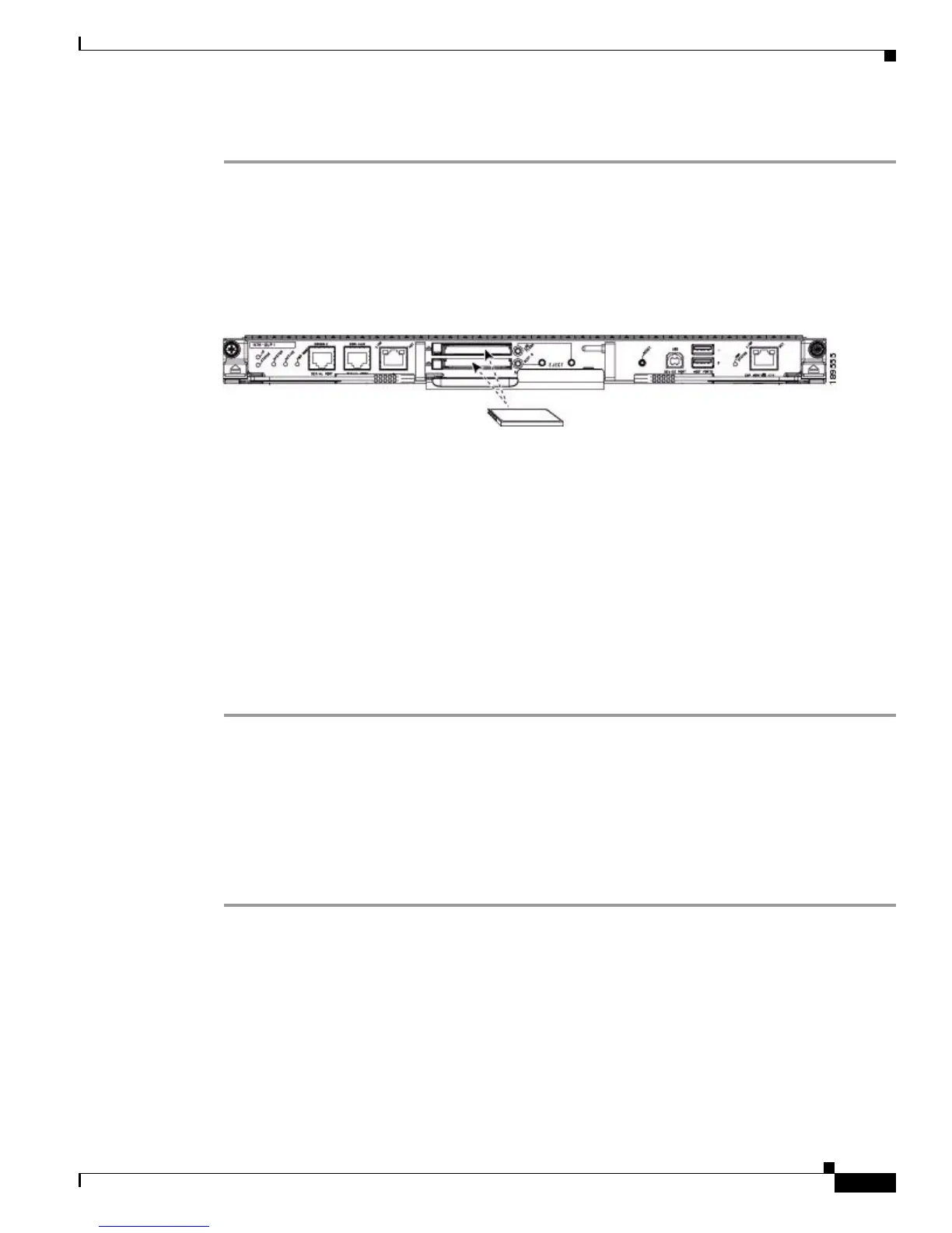
To install storage media in a supervisor module, follow these steps:
Step 1 Align the storage media to its slot or port on the supervisor module as follows:
• For a Supervisor 1 module, align the card with the slot for the CompactFlash reader slot labeled
LOG FLASH or EXPANSION FLASH as shown in Figure 4-10. The grooves on the thin side of the
card are on the end of the card that goes into the reader first. If the card does not fit easily into the
reader, flip the card so that the bottom edge is on top, and try pushing the card into the reader.
Figure 4-10 Aligning a CompactFlash Card to its Reader
• For a Supervisor 2 or 2E module, insert the USB drive in the LOG FLASH or SLOT0 port.
Step 2 Wait for the reader or port LED to turn green and for a message to appear on the console as follows:
• If you are installing a card or USB drive into the log flash reader, the message will end with
“logflash:online.”
• If you are installing a card or USB drive into the expansion flash reader, the message will end with
“slot0:online.”
• If you see an “offline” message or do not see a message, either the card or USB drive is not fully
inserted or it is improperly formatted.
Make sure that the card or USB drive is fully inserted inside the reader. If it is fully inserted, either
format the card (see the Cisco Nexus 7000 Series NX-OS Fundamentals Configuration Guide) or
replace the storage media with another that is properly formatted for the reader.
Installing the Front Doors and Frame Assembly
After you have finished moving the chassis to its rack, you can install its optional front doors and frame
assemblies.
To install the front doors and frame assemblies, follow these steps:
Step 1 Align the bottom frame assembly so that its four screw holes align to screw holes in the bottom of the
chassis, and then screw in four M4 x 6 mm screws to attach the bottom frame to the chassis (see
Figure 4-11).
 Loading...