1-9
Cisco Nexus 7000 Series Hardware Installation and Reference Guide
OL-23069-07
Chapter 1 Overview
Cisco Nexus 7000 Series
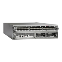
Note Figure 1-2 and Figure 1-3 show the Cisco Nexus 7009 chassis as it appears when it is fully configured
before including cables for management and network connections. The systems that are not fully
configured with the maximum number of supervisor modules, I/O modules, fabric modules, or power
supplies have blank panels installed in place of the missing components to maintain the designed airflow
for system cooling.
You must install the Cisco Nexus 7009 chassis in a two- or four-post 19-inch EIA rack that meets the
following specifications:
• Mounting rails that conform to the English universal hole spacing as specified in
ANSI/EIA-310-D-1992.
• The minimum vertical rack space is 24.5 inches (62.2 cm) or 14 rack units (RU) for a single chassis
installation (15 RU if you use the bottom support rails, which are required for center-mount
installations and optional for front-mount installations).
Install the Cisco Nexus 7009 chassis at the lowest possible RU on the rack for stability. If there are other
devices in the rack, install the heaviest chassis below the lighter chassis.
Warning
Stability hazard. The rack stabilizing mechanism must be in place, or the rack must be bolted to the
floor before you slide the unit out for servicing. Failure to stabilize the rack can cause the rack to tip
over.
Statement 1048
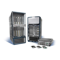
Cisco Nexus 7010 System
The Cisco Nexus 7010 chassis has 10 slots that allow for two supervisor modules and up to eight I/O
modules. Additionally, the chassis holds up to five fabric modules, two system fan trays, two fabric fan
trays, up to three power supplies, and cable management frames. The chassis also has mounting brackets
and four positioning handles (two on each side) that you use to install the chassis after you position it
on a rack. Optionally, you can include an air filter and mid-frame doors.
Figure 1-4 identifies the standard features on the front and sides of the Cisco Nexus 7010 chassis,
Figure 1-5 identifies the optional features on the front side of the chassis, and Figure 1-6 identifies the
standard features on the rear of the chassis.
 Loading...