A-37
Cisco Nexus 7000 Series Hardware Installation and Reference Guide
OL-23069-07
Appendix A Technical Specifications
Chassis Airflow
Chassis Airflow
The Cisco Nexus 7000 Series switches are designed to work in a hot-aisle/cold-aisle environment using
front-to-back, side-to-side, or side-to-back airflow. Each of these switches uses one of the following
airflow directions:
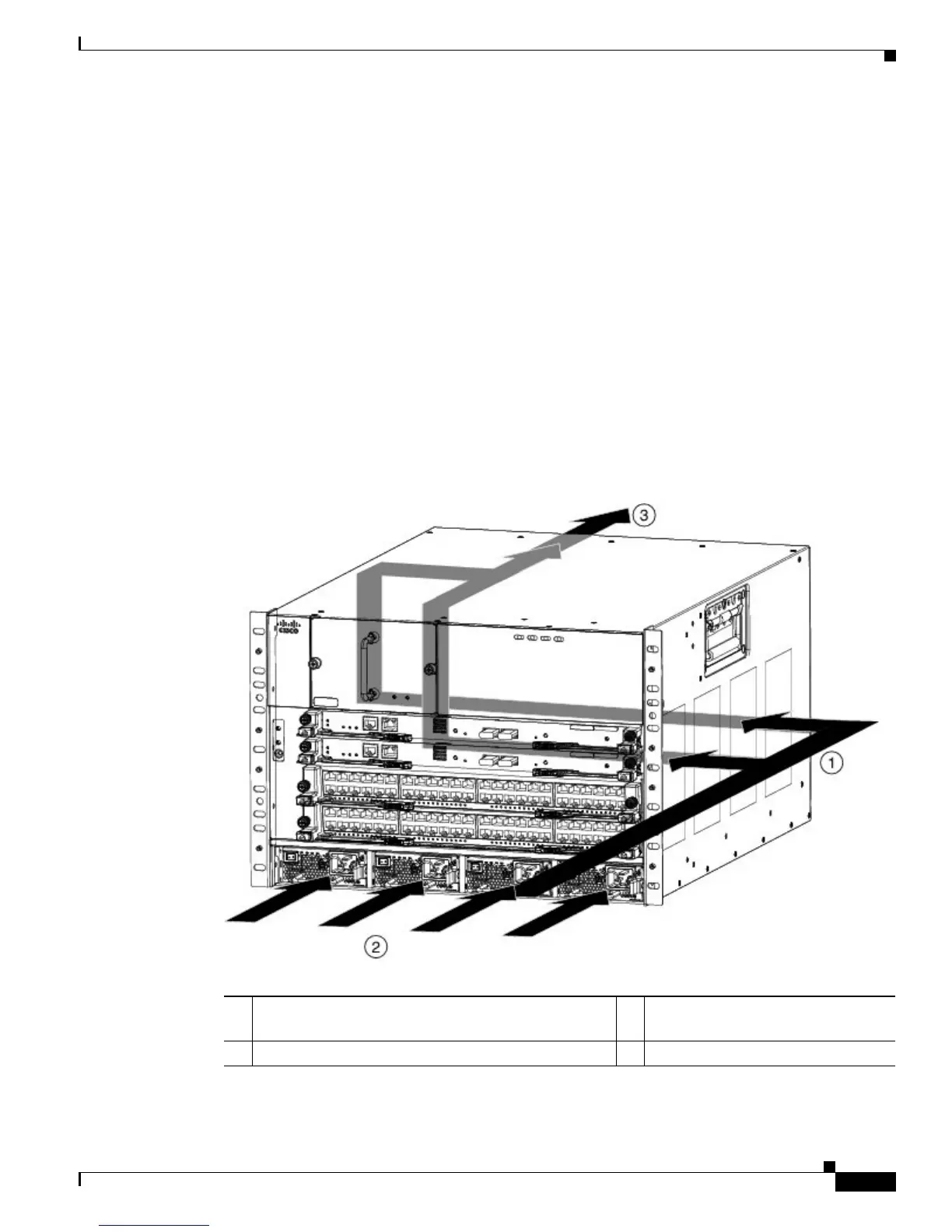
• The Cisco Nexus 7004 switch uses side-to-back airflow to cool its modules and front-to-back
airflow to cool its power supplies as shown in Figure A-22. This switch requires right-side clearance
for airflow into the chassis.
• The Cisco Nexus 7009 switch uses side-to-side airflow to cool its modules and front-to-back airflow
to cool its power supplies as shown in Figure A-23. This switch requires right- and left-side
clearance for airflow into and out of the chassis.
• The Cisco Nexus 7010 switch uses front-to-back airflow as shown in Figure A-24.
• The Cisco Nexus 7018 switch uses side-to-side airflow to cool its modules and front-to-back airflow
to cool its power supply units as shown in Figure A-25. This switch requires right- and left-side
clearance for airflow into and out of the chassis.
Figure A-22 Airflow for the Cisco Nexus 7004 Chassis
1 Right side-to-rear airflow for cooling supervisor and
I/O modules
3 Exhaust out the rear to the hot aisle
2 Front-to-rear airflow for cooling power supplies
 Loading...