Hardware Overview 43
3 Installing the Hardware
Rear Panel Description
The AC power connector is a standard three-pronged connector that supports the power cord.
Plug the female connector of the provided power cord into this socket, and plug the male side
of the cord into a power outlet. The Switch automatically adjusts its power setting to any
supply voltage in the range from 100 ~ 240 VAC at 50 ~ 60 Hz.
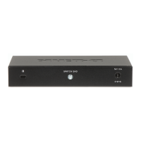
The rear panel also includes an outlet for an optional external power supply. When a power
failure occurs, the optional external RPS will immediately and automatically assume the
power supply for the Switch.
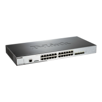
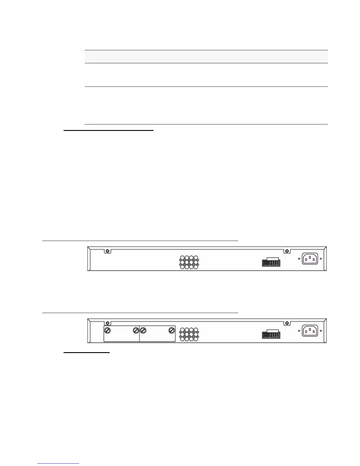
The rear panel of the DWS-3024/DWS-3024L contains an AC power connector, a system fan
vent, and a redundant power supply connector.
Figure 17. Rear panel view of DWS-3024/DWS-3024L
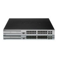
The rear panel of the DWS-3026 contains an AC power connector, a system fan vent, a
redundant power supply connector and two empty slots for optional 10GE module inserts.
Figure 18. Rear panel view of DWS-3026
Side Panels
The system fans and heat vents located on each side of the Switch dissipate heat. Do not block
these openings. Leave at least 6 inches of space at the rear and sides of the Switch for proper
ventilation. Without proper heat dissipation and air circulation, system components might
overheat, which could lead to system failure and severely damage components.
10GE Port LEDs (DWS-3026 only) A steady green light denotes a valid link on the port while
a blinking green light indicates activity on the port. These LEDs remain dark
if there is no link/activity on the port.
Combo SFP Ports The LED indicators for the Combo ports are located above the ports and
numbered 1 – 4 for Combo 1, Combo 2, Combo 3, and Combo 4 ports. A
steady green light indicates a valid link on the port while a blinking green
light indicates activity on the port. These LEDs remain dark if there is no
link/activity on the port.
Table 2. LED Description
LED Description
 Loading...