MB95630H Series
MN702-00009-2v0-E FUJITSU SEMICONDUCTOR LIMITED 89
CHAPTER 7 TIME-BASE TIMER
7.2 Configuration
7.2 Configuration
The time-base timer consists of the following blocks:
• Time-base timer counter
• Counter clear circuit
• Interval timer selector
• Time-base timer control register (TBTC)
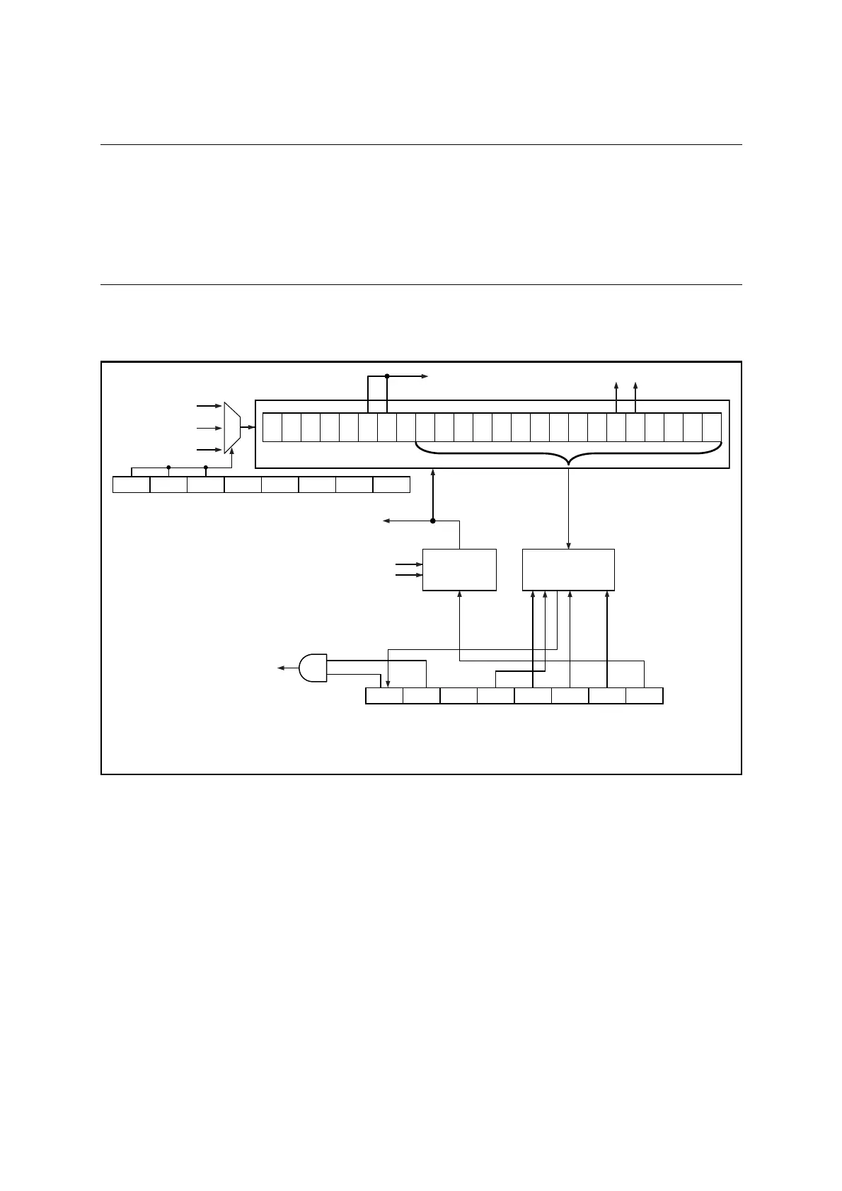
■ Block Diagram of Time-base Timer
Figure 7.2-1 Block Diagram of Time-base Timer
Time-base timer counter
Counter clear
To prescaler
To software watchdog timer
Counter
clear circuit
Interval timer
selector
Time-base timer control register (TBTC)
Resets
Software watchdog timer clear
Time-base timer interrupt
FCH
FCRH
FCRH
FCH divided by 2
System clock control register (SYCC)
SCM2 SCM1 SCM0 SCS2 SCS1 SCS0 DIV1 DIV0
TBIF TBIE - TBC3 TBC2 TBC1 TBC0 TCLR
: Main CR clock
: Main clock
F
MCRPLL : Main CR PLL clock
Stops main clock oscillation or main CR clock oscillation
FMCRPLL
×2
1
×2
2
×2
3
×2
4
×2
5
×2
6
×2
7
×2
8
×2
9
×2
10
×2
11
×2
12
×2
13
×2
14
×2
15
×2
16
×2
17
×2
18
×2
19
×2
20
×2
21
×2
22
×2
23
×2
24
 Loading...

