MB95630H Series
MN702-00009-2v0-E FUJITSU SEMICONDUCTOR LIMITED 363
CHAPTER 20 16-BIT RELOAD TIMER
20.6 Operations and Setting Procedure Example
20.6.1 Internal Clock Mode
In this mode, the 16-bit downcounter counts down while being synchronized
with the internal count clock, and outputs an interrupt request to the interrupt
controller every time an underflow occurs ("0x0000" → "0xFFFF"). In addition,
the TOn pin can output the toggle waveform.
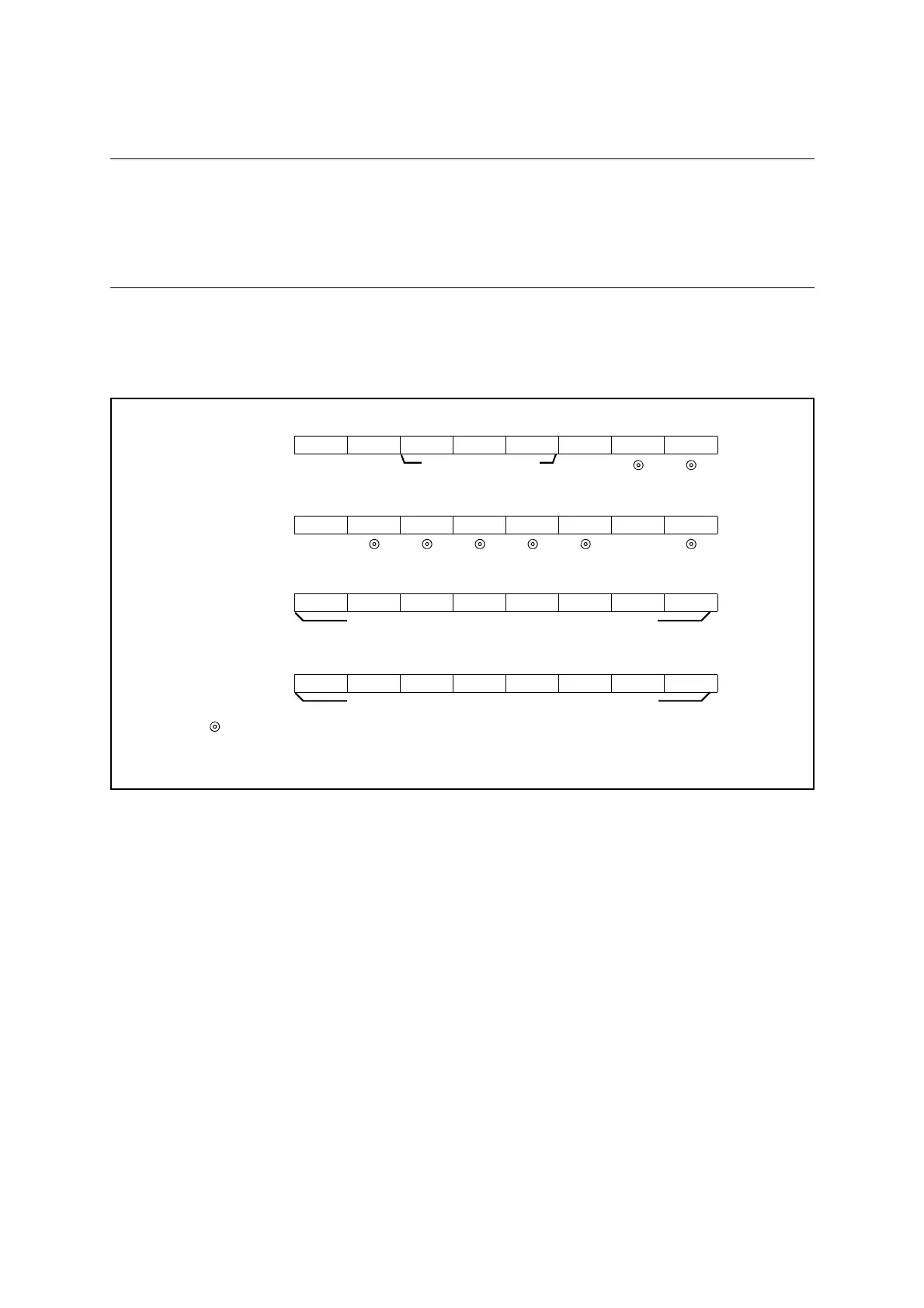
■ Setting Internal Clock Mode
The timer requires the register settings shown in Figure 20.6-2 to operate as an interval timer.
Figure 20.6-2 Internal Clock Mode Setup
■ Operation of Internal Clock Mode (Reload Mode)
When "1" is set to the count enable bit (CNTE) to enable counting, and the timer is started by
setting "1" to the software trigger bit (TRG) or by an external trigger, the value set in the 16-bit
reload timer reload register (upper/lower) ch. n (TMRLRHn/TMRLRLn) is reloaded to the 16-
bit downcounter and downcounting starts. If counting is enabled when the count enable bit
(CNTE) and software trigger bit (TRG) are set to "1" at the same time, the counting starts at the
same time.
If the reload select bit (RELD) is "1", the value of the 16-bit reload timer reload register
(upper/lower) ch. n (TMRLRHn/TMRLRLn) is reloaded to the 16-bit downcounter and the
count continues when the 16-bit counter underflows ("0x0000" → "0xFFFF"). If the underflow
interrupt request flag bit (UF) is "1" when the underflow interrupt request enable bit (INTE) is
set to "1", an interrupt request is output.
The TOn pin can output a toggle waveform that is inverted every time an underflow occurs.
bit7 bit6 bit5 bit4 bit3 bit2 bit1 bit0
TMCSRHn - - CSL2 CSL1 CSL0 MOD2 MOD1 MOD0
0
bit7 bit6 bit5 bit4 bit3 bit2 bit1 bit0
TMCSRLn - OUTE OUTL RELD INTE UF CNTE TRG
01
bit7 bit6 bit5 bit4 bit3 bit2 bit1 bit0
TMRLRHn D15 D14 D13 D12 D11 D10 D9 D8
bit7 bit6 bit5 bit4 bit3 bit2 bit1 bit0
TMRLRLnD7D6D5D4D3D2D1D0
: Used bit
0 : Set to "0"
1 : Set to "1"
Set initial value of counter (reload value) (upper)
Set initial value of counter (reload value) (lower)