MB95630H Series
MN702-00009-2v0-E FUJITSU SEMICONDUCTOR LIMITED 227
CHAPTER 14 LIN-UART
14.6 Operations of LIN-UART and LIN-UART
Setting Procedure Example
14.6.2 Operations in Synchronous Mode
(Operating Mode 2)
When the LIN-UART is used in operating mode 2 (normal mode), the transfer
method is clock synchronous transfer.
■ Operations in Synchronous Mode (Operating Mode 2)
● Transmit/receive data format
In synchronous mode, 8-bit data is transmitted and received; the addition of the start bit and of
the stop bit can be selected (ECCR:SSM). When the start/stop bits are added to the data format
(ECCR:SSM = 1), the addition of the parity bit can also be selected (SCR:PEN).
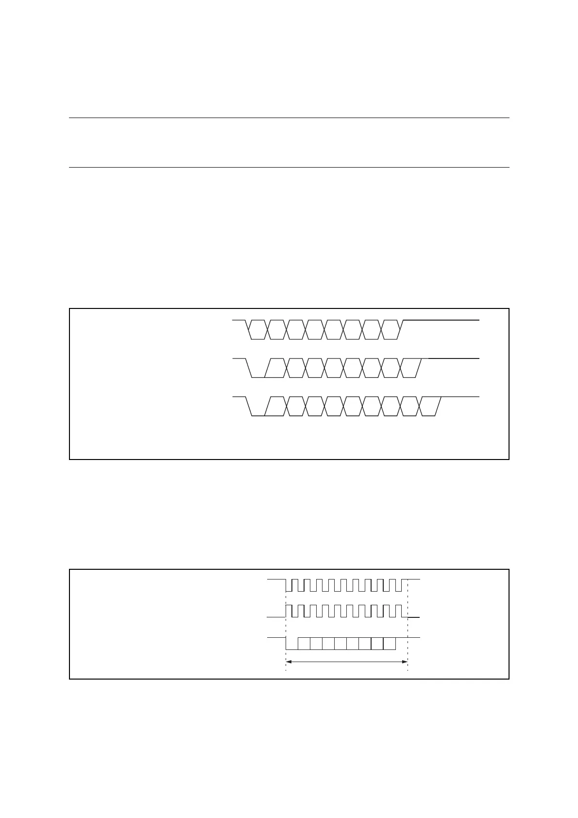
Figure 14.6-3 shows the data format in synchronous mode (operating mode 2).
Figure 14.6-3 Transmit/Receive Data Format (Operating Mode 2)
● Clock inversion function
When the SCES bit in the LIN-UART extended status control register (ESCR) is "1", the serial
clock is inverted. In the case of serial clock reception side is selected, the LIN-UART samples
data at the falling edge of the received serial clock. In the case of serial clock transmission side
is selected, the mark level is set to "0" when the SCES bit is "1".
Figure 14.6-4 Transmission Data Format During Clock Inverted
● Start/stop bits
When the SSM bit in the LIN-UART extended communication control register (ECCR) is "1",
the start and stop bits are added to the data format as they are in asynchronous mode.
*
*
(ECCR:SSM=0,SCR:PEN=0)
(ECCR:SSM=1,SCR:PEN=0)
(ECCR:SSM=1,SCR:PEN=1)
D0 D1 D2 D3 D4 D5 D6 D7
STD0 D1D2D3 D4 D5 D6 D7
STD0 D1D2 D3 D4 D5 D6 D7 P SP SP
SP SP
Transmit/receive data
Transmit/receive data
Transmit/receive data
*: When two stop bits are used (SCR:SBL = 1)
ST: Start bit, SP: Stop bit, P: Parity bit Data bit transfer method: LSB-first
Data frame
Transmit/receive clock
Data stream (SSM = 1)
(No parity, 1 stop bit)
ST
SP
(SCES = 0, CCO = 0)
Transmit/receive clock
(SCES = 1, CCO = 0)
Mark level
Mark level
 Loading...

