MB95630H Series
MN702-00009-2v0-E FUJITSU SEMICONDUCTOR LIMITED 9
CHAPTER 2 CPU
2.1 Dedicated Registers
2.1.3 Condition Code Register (CCR)
The condition code register (CCR) in the lower eight bits of the program status
(PS) register consists of the bits (H, N, Z, V, and C) containing information
about the arithmetic result or transfer data and the bits (I, IL1, and IL0) used to
control the acceptance of interrupt requests.
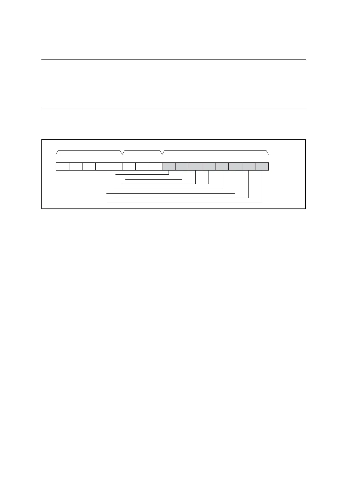
■ Configuration of Condition Code Register (CCR)
Figure 2.1-5 Configuration of Condition Code Register (CCR)
The condition code register is a part of the program status (PS) register and therefore cannot be
accessed independently.
■ Bits Showing Operation Results
● Half carry flag (H)
This flag is set to "1" when a carry from bit3 to bit4 or a borrow from bit4 to bit3 occurs due to
the result of an operation. Otherwise, the flag is set to "0". Do not use this flag for any
operation other than addition and subtraction as the flag is intended for decimal-adjusted
instructions.
● Negative flag (N)
This flag is set to "1" when the value of the most significant bit is "1" due to the result of an
operation, and is set to "0" when the value of the most significant bit is "0".
● Zero flag (Z)
This flag is set to "1" when the result of an operation is "0", and is set to "0" when the result of
an operation is a value other than "0".
● Overflow flag (V)
This flag indicates whether the result of an operation has caused an overflow, with the operand
used in the operation being regarded as an integer expressed as a complement of two. If an
overflow occurs, the overflow flag is set to "1"; otherwise, it is set to "0".
Half carry flag
Interrupt enable flag
Interrupt level bits
Negative flag
Zero flag
Overflow flag
Carry flag
CCRDPRP
PS 0b00110000
CCR
initial value
R4 R3 R2 R1 R0 DP2 DP1 DP0 H I IL1 IL0 N Z V C
bit15 bit14 bit13bit12 bit11 bit10 bit9 bit8bit7 bit6 bit5 bit4 bit3bit2 bit1 bit0