MB95630H Series
240 FUJITSU SEMICONDUCTOR LIMITED MN702-00009-2v0-E
CHAPTER 14 LIN-UART
14.6 Operations of LIN-UART and LIN-UART
Setting Procedure Example
14.6.7 LIN Communication Function
In LIN-UART communication, a LIN device can be used in a LIN master system
or a LIN slave system.
■ LIN Master/Slave Mode Communication Function
Figure 14.6-16 shows the required settings for the LIN communication mode (operating mode
3) of the LIN-UART.
Figure 14.6-16 Settings of LIN-UART Operating Mode 3 (LIN)
● LIN device connection
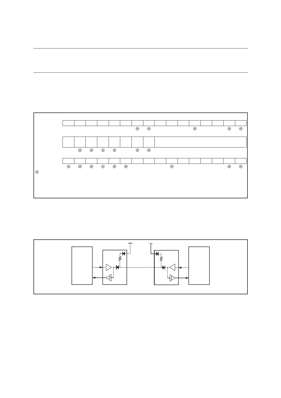
Figure 14.6-17 shows an example of communication in a LIN bus system.
The LIN-UART can operate as a LIN master or a LIN slave.
Figure 14.6-17 Example of LIN Bus System Communication
bit15 bit14 bit13 bit12 bit11 bit10 bit9 bit8 bit7 bit6 bit5 bit4 bit3 bit2 bit1 bit0
SCR, SMR PEN P SBL CL AD CRE RXE TXE MD1 MD0 OTO EXT
REST UPCL SCKE
SOE
Mode 3 → +×++×0 110 00
SSR,
RDR/TDR
PE ORE FRE
RDRF TDRE
BDS RIE TIE
Set conversion data (during writing)
Retain reception data (during reading)
Mode 3 → ×+
ESCR, ECCR LBIE LBD LBL1 LBL0
SOPE
SIOP CCO
SCES
Reserved
LBR MS
SCDE
SSM
Reserved
RBI TBI
Mode 3 → 000 ×××0
: Bit to be used
× : Unused bit
1 : Set to "1"
0 : Set to "0"
+ : Bit correctly set automatically
SOT
SIN
SOT
SIN
LIN master Transceiver
LIN bus
Transceiver LIN slave
 Loading...

