MB95630H Series
MN702-00009-2v0-E FUJITSU SEMICONDUCTOR LIMITED 189
CHAPTER 13 INTERRUPT PIN SELECTION CIRCUIT
13.2 Configuration
13.2 Configuration
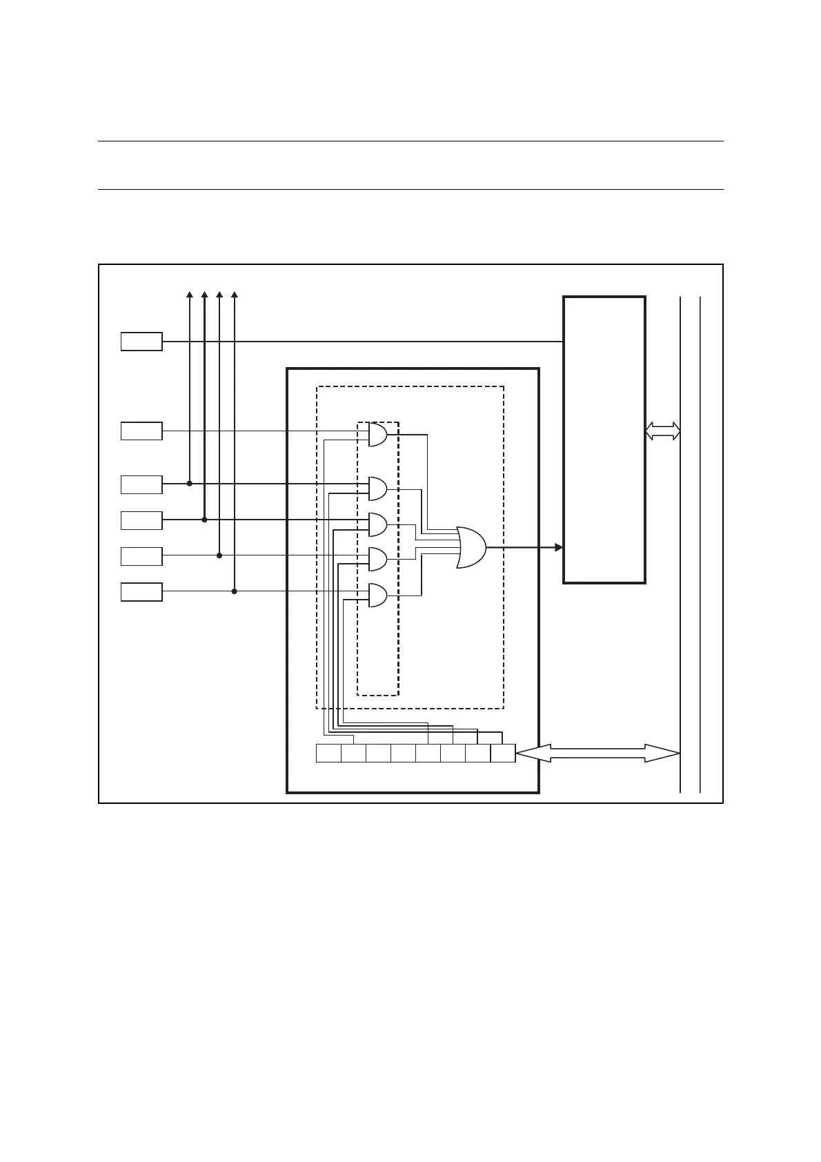
Figure 13.2-1 shows the block diagram of the interrupt pin selection circuit.
■ Block Diagram of Interrupt Pin Selection Circuit
Figure 13.2-1 Block Diagram of Interrupt Pin Selection Circuit
• WICR register (interrupt pin selection circuit control register)
This register is used to determine which of the available peripheral input pins should be
output to the interrupt circuit and which interrupt pins they should serve as.
• Selection circuit
This circuit outputs the input from the pin selected by the WICR register to the INT00 input
of the external interrupt circuit (ch. 0).
P01
INT01
External
interrupt circuit
INT01
INT00
(Unit 0)
Interrupt pin selection circuit
To each peripheral function
Selection circuit
P14
P00
INT00
P16
P64
P67
UCK0
UI0
EC1
TRG1
WICR register
Internal data bus
 Loading...

