MB95630H Series
154 FUJITSU SEMICONDUCTOR LIMITED MN702-00009-2v0-E
CHAPTER 11 8/16-BIT COMPOSITE TIMER
11.11 Operation of PWC Timer Function
11.11 Operation of PWC Timer Function
This section describes the operation of the PWC timer function of the 8/16-bit
composite timer.
■ Operation of PWC Timer Function
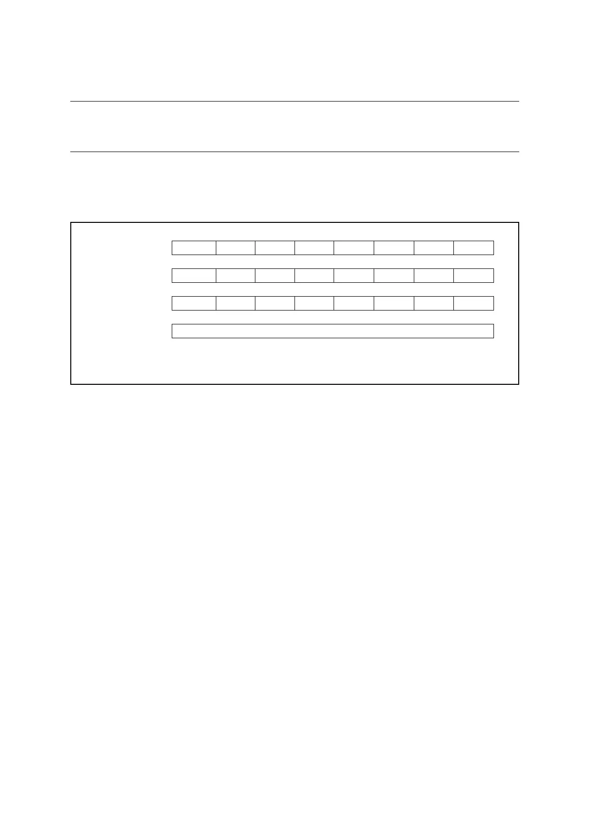
To use the PWC timer function, do the settings shown in Figure 11.11-1.
Figure 11.11-1 Settings for PWC Timer Function
When the PWC timer function is selected, the width and cycle of an external input pulse can be
measured. The edges at which counting starts and ends are selected by the timer operating
mode select bits (Tn0CR0/Tn1CR0:F[3:0]).
In the operation of this function, the counter starts counting from "0x00" immediately after a
specified count start edge of an external input signal is detected. Upon the detection of a
specified count end edge, the count value is transferred to the 8/16-bit composite timer data
register (Tn0DR/Tn1DR), and the interrupt flag (Tn0CR1/Tn1CR1:IR) and the buffer full flag
(Tn0CR1/Tn1CR1:BF) are set to "1". The buffer full flag is set to "0" when the 8/16-bit
composite timer data register (Tn0DR/Tn1DR) is read.
If the buffer full flag is set to "1", the 8/16-bit composite timer data register holds data. Even if
the next edge is detected during that time, the next measurement result is lost since the count
value has not been transferred to the 8/16-bit composite timer data register.
There is an exception. With the F3 bit to F0 bit in the Tn0CR0/Tn1CR0 register having been
set to "1001
B
", even though the BF bit is set to "1", the "H" pulse measurement result is
transferred to the 8/16-bit composite timer data register, while the cycle measurement result is
not transferred to the 8/16-bit composite timer data register. Therefore, in order to perform
cycle measurement, the "H" pulse measurement result must be read before a cycle is
completed. In addition, the result of "H" pulse measurement and that of cycle measurement are
lost if they are not read before the completion of the next "H" pulse.
The time exceeding the range of the counter can be measured by counting the number of
counter overflows using the software. When the counter overflows, the interrupt flag (Tn0CR1/
Tn1CR1:IF) is set to "1". The interrupt service routine can therefore be used to count the
number of overflows. In addition, the timer output is inverted due to the overflow. The timer
output initial value can be set by the timer output initial value bit (Tn0CR1/Tn1CR1:SO).
When the timer stops operating, the timer output bit (TMCRn:TO1/TO0) holds the last value.
bit7 bit6 bit5 bit4 bit3 bit2 bit1 bit0
Tn0CR0/Tn1CR0 IFE C2 C1 C0 F3 F2 F1 F0
❍ ❍❍❍❍❍❍❍
Tn0CR1/Tn1CR1 STA HO IE IR BF IF SO OE
1 ❍❍❍❍❍❍ ×
TMCRn TO1 TO0 TIS MOD FE11 FE10 FE01 FE00
❍ ❍❍❍❍❍❍❍
Tn0DR/Tn1DR Holds pulse width measurement value
❍: Bit to be used
×: Unused bit
1: Set to "1"