MB95630H Series
148 FUJITSU SEMICONDUCTOR LIMITED MN702-00009-2v0-E
CHAPTER 11 8/16-BIT COMPOSITE TIMER
11.8 Operation of Interval Timer Function
(Free-run Mode)
11.8 Operation of Interval Timer Function
(Free-run Mode)
This section describes the operation of the interval timer function (free-run
mode) of the 8/16-bit composite timer.
■ Operation of Interval Timer Function (Free-run Mode)
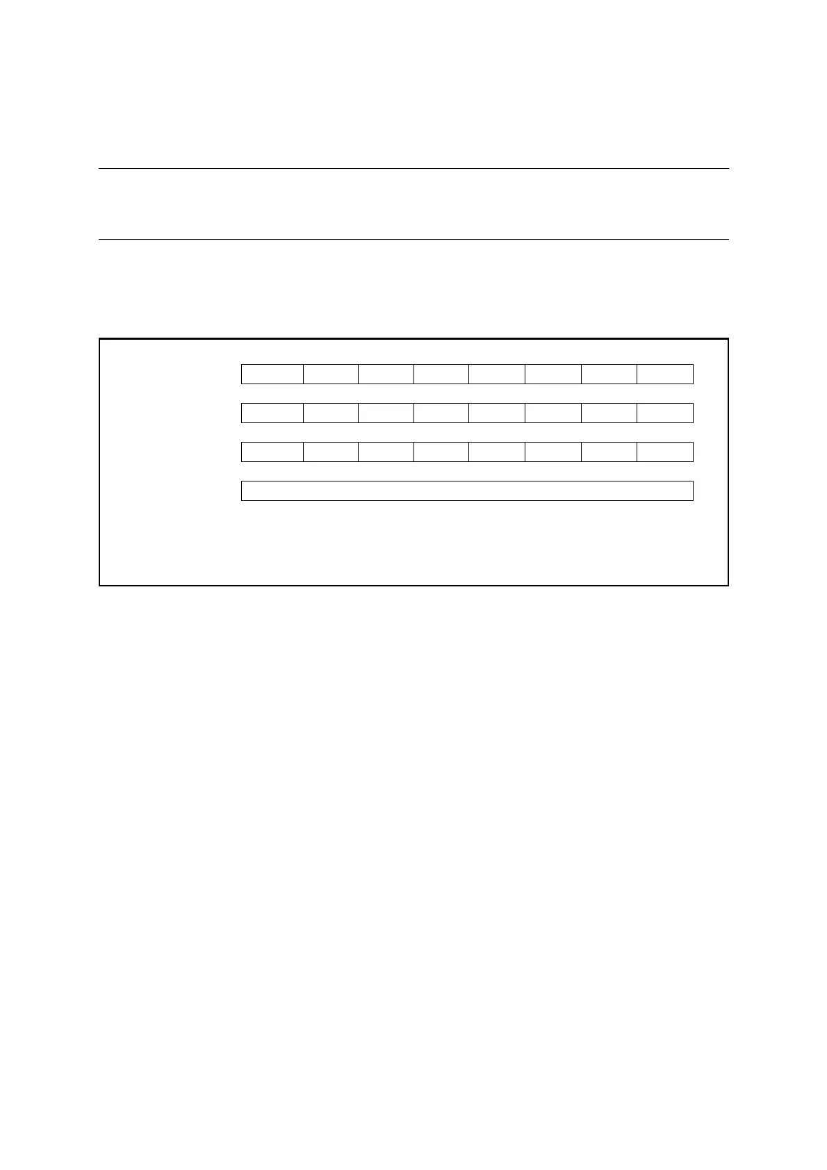
To use the interval timer function (free-run mode), do the settings shown in Figure 11.8-1.
Figure 11.8-1 Settings for Interval Timer Function (Free-run Mode)
As for the interval timer function (free-run mode), enabling timer operation (Tn0CR1/
Tn1CR1:STA = 1) causes the counter to start counting from "0x00" at the rising edge of a
selected count clock signal. When the counter value matches the value in the 8/16-bit
composite timer data register (Tn0DR/Tn1DR), the timer output bit (TMCRn:TO0/TO1) is
inverted and the interrupt flag (Tn0CR1/Tn1CR1:IF) is set to "1". If the counter continues to
count with the above settings and then reaches "0xFF", it returns to "0x00" and restarts
counting. The timer outputs square wave as a result of this continuous operation.
The value of the 8/16-bit composite timer data register (Tn0DR/Tn1DR) is transferred to the
temporary storage latch (comparison data storage latch) in the comparator either when the
counter starts counting or when a counter value comparison match is detected. Do not write
"0x00" to the 8/16-bit composite timer data register.
When the timer stops operation, the timer output bit (TMCRn:TO0/TO1) holds the last value.
bit7 bit6 bit5 bit4 bit3 bit2 bit1 bit0
Tn0CR0/Tn1CR0 IFE C2 C1 C0 F3 F2 F1 F0
❍❍❍❍0010
Tn0CR1/Tn1CR1 STA HO IE IR BF IF SO OE
1 ❍❍ ××❍❍❍
TMCRn TO1 TO0 TIS MOD FE11 FE10 FE01 FE00
❍❍× ❍❍❍❍❍
Tn0DR/Tn1DR Sets interval time (counter compare value)
❍: Bit to be used
×: Unused bit
1: Set to "1"
0: Set to "0"