MB95630H Series
MN702-00009-2v0-E FUJITSU SEMICONDUCTOR LIMITED 235
CHAPTER 14 LIN-UART
14.6 Operations of LIN-UART and LIN-UART
Setting Procedure Example
14.6.5 Bidirectional Communication Function
(Normal Mode)
Normal serial bidirectional communication can be performed in operating mode
0 or 2. Asynchronous mode can be selected in operating mode 0 and
synchronous mode in operating mode 2.
■ Bidirectional Communication Function
To operate the LIN-UART in normal mode (operating mode 0 or 2), the settings shown in
Figure 14.6-10 are required.
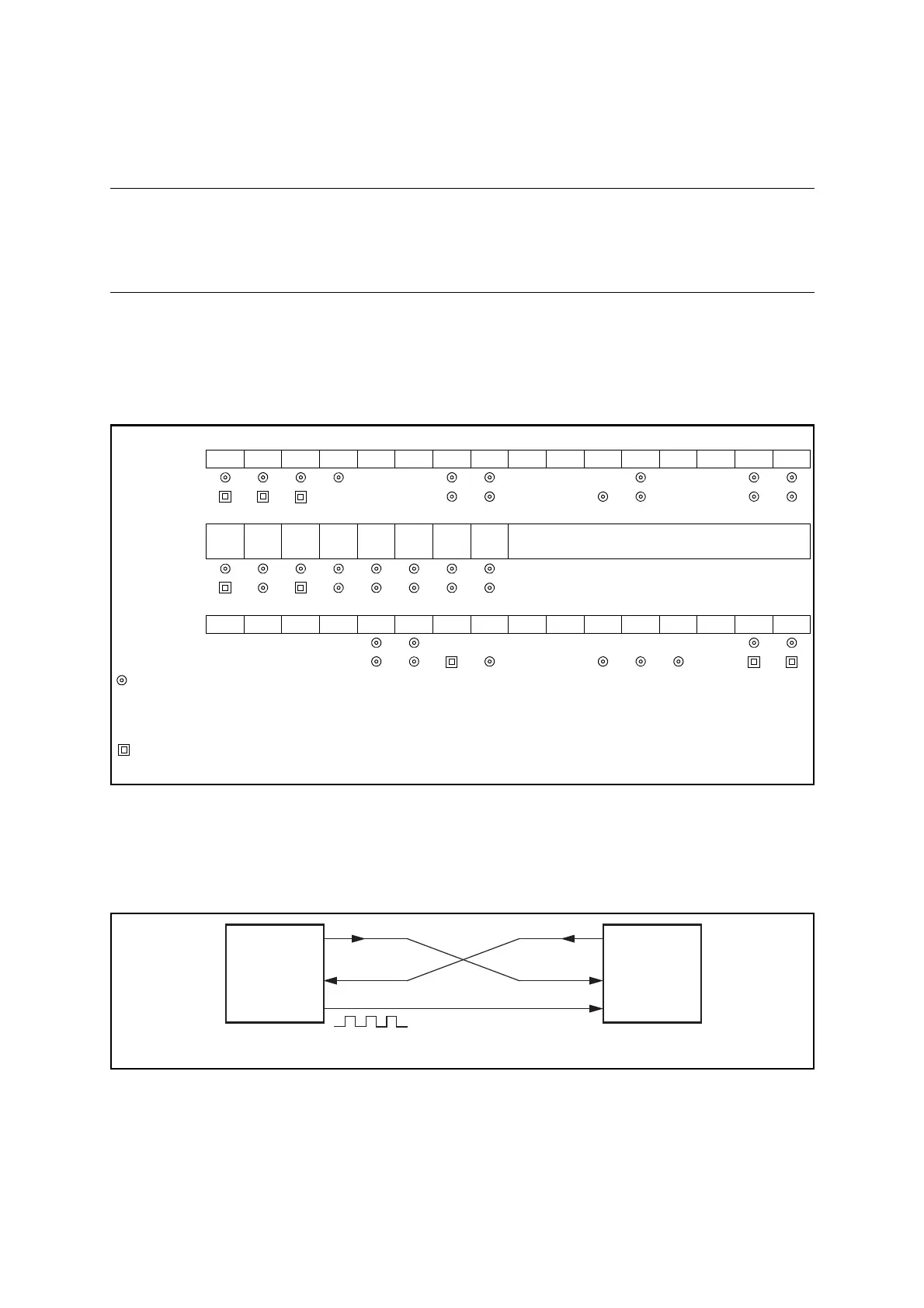
Figure 14.6-10 Settings of LIN-UART Operating Mode 0 and Operating Mode 2
● Inter-CPU connection
When using bidirectional communication, connect two CPUs as shown in Figure 14.6-11.
Figure 14.6-11 Example of Connection for Bidirectional Communication in LIN-UART Operating
Mode 2
bit15 bit14 bit13 bit12 bit11 bit10 bit9 bit8 bit7 bit6 bit5 bit4 bit3 bit2 bit1 bit0
SCR, SMR PEN P SBL CL AD CRE RXE TXE MD1 MD0 OTO EXT
REST UPCL SCKE
SOE
Mode 0 → ×0 000 00
Mode 2 → +×01000
SSR,
RDR/TDR
PE ORE FRE
RDRF
TDRE
BDS RIE TIE
Set conversion data (during writing)
Retain reception data (during reading)
Mode 0 →
Mode 2 →
ESCR, ECCR LBIE LBD LBL1 LBL0
SOPE
SIOP CCO
SCES
Reserved
LBR MS
SCDE
SSM
Reserved
RBI TBI
Mode 0 → ×××× 0000×××0
Mode 2 → ×××× 0× 0
: Bit to be used
× : Unused bit
1 : Set to "1"
0 : Set to "0"
: Used when SSM = 1 (Synchronous star/stop bit mode)
+ : Bit correctly set automatically
SOT
SIN
SCK
SOT
SIN
SCK
Input
Output
CPU1
(Serial clock transmit side)
CPU2
(Serial clock receive side)
 Loading...

