MB95630H Series
MN702-00009-2v0-E FUJITSU SEMICONDUCTOR LIMITED 211
CHAPTER 14 LIN-UART
14.4 Interrupts
14.4.2 Timing of Transmit Interrupt Generation and Flag
Set
A transmit interrupt is generated when transmit data is transferred from the
LIN-UART transmit data register (TDR) to the transmit shift register and then
data transmission starts.
■ Timing of Transmit Interrupt Generation and Flag Set
When the data written to the LIN-UART transmit data register (TDR) is transferred to the
transmit shift register and the transmission of that data starts, the next data can be written to the
TDR register (SSR:TDRE = 1). At the start of the data transmission, if the transmit interrupt
has been enabled (SSR:TIE = 1), a transmit interrupt is generated.
The TDRE bit is a read-only bit, and is cleared to "0" only when data is written to the LIN-
UART transmit data register (TDR).
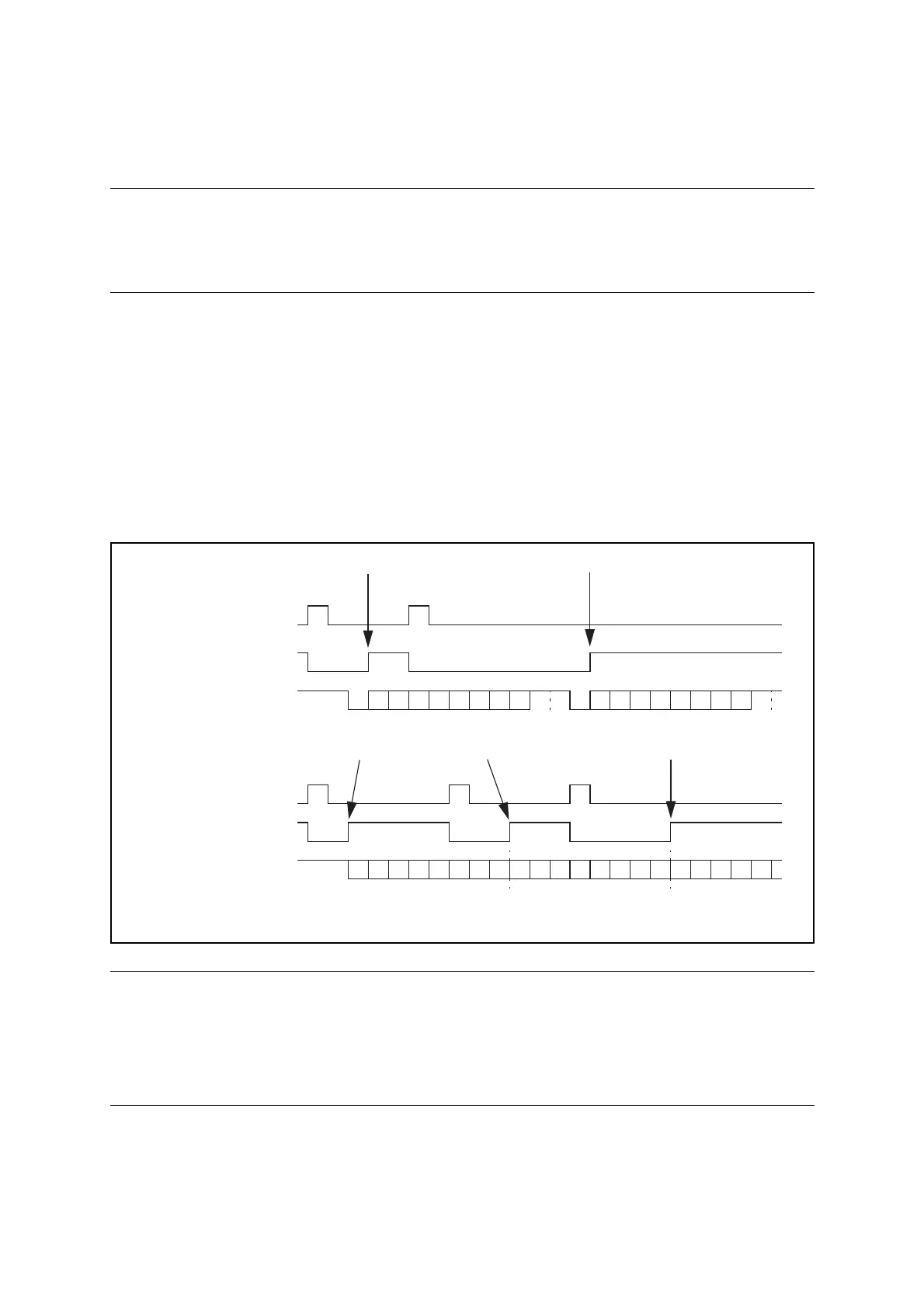
Figure 14.4-4 shows the timing of transmission and flag set.
Figure 14.4-4 Timing of Transmission and Flag Set
Note:
Figure 14.4-4 does not show all transmission operations in operating mode 0. It only
shows an example of a transmission operation using 8-bit data, a parity bit ("even parity"
or "odd parity") and one stop bit.
No parity bit is transmitted in operating mode 3, or in operating mode 2 with SSM = 0.
TDRE
TDRE
STD0D1D2D3 D4 D5 D6 D7
P
AD
SP STD0D1D2D3 D4 D5 D6 D7
P
AD
SP
D0 D1 D2 D3 D4 D5 D6 D7 D0 D1 D2 D3 D4 D5 D6 D7 D0 D1 D2 D3 D4
Transmit interrupt generated Transmit interrupt generated
Transmit interrupt generated Transmit interrupt generated
Mode 0/1/3:
Write to TDR
Serial output
Mode 2 (SSM = 0):
Write to TDR
Serial output
ST: Start bit, D0 to D7: Data bits, P: Parity, SP: Stop bit
AD: Address data selection bit (mode 1)