MB95630H Series
206 FUJITSU SEMICONDUCTOR LIMITED MN702-00009-2v0-E
CHAPTER 14 LIN-UART
14.4 Interrupts
14.4 Interrupts
The LIN-UART has receive interrupts and transmit interrupts, which are
generated by the following sources. An interrupt number and an interrupt
vector are assigned to each interrupt. In addition, it has a LIN synch field edge
detection interrupt function using the 8/16-bit composite timer interrupt.
• Receive interrupt
A receive interrupt occurs when received data is set in the LIN-UART receive
data register (RDR), or when a receive error occurs, or when a LIN synch
break is detected.
• Transmit interrupt
A transmit interrupt occurs when transmit data is transferred from the LIN-
UART transmit data register (TDR) to the transmit shift register, and data
transmission starts.
■ Receive Interrupt
Table 14.4-1 shows the control bits and interrupt sources of receive interrupts.
● Receive interrupts
If one of the following operations occurs in reception mode, the bit in the LIN-UART serial
status register (SSR) corresponding to that operation is set to "1".
Data reception completed
Received data is transferred from the LIN-UART serial input shift register to the LIN-UART
receive data register (RDR) (RDRF = 1).
Overrun error
With RDRF = 1, the next serial data is received while the CPU has not read the RDR
register. (ORE = 1).
Framing error
A stop bit reception error occurs (FRE = 1).
Parity error
A parity detection error occurs (PE = 1).
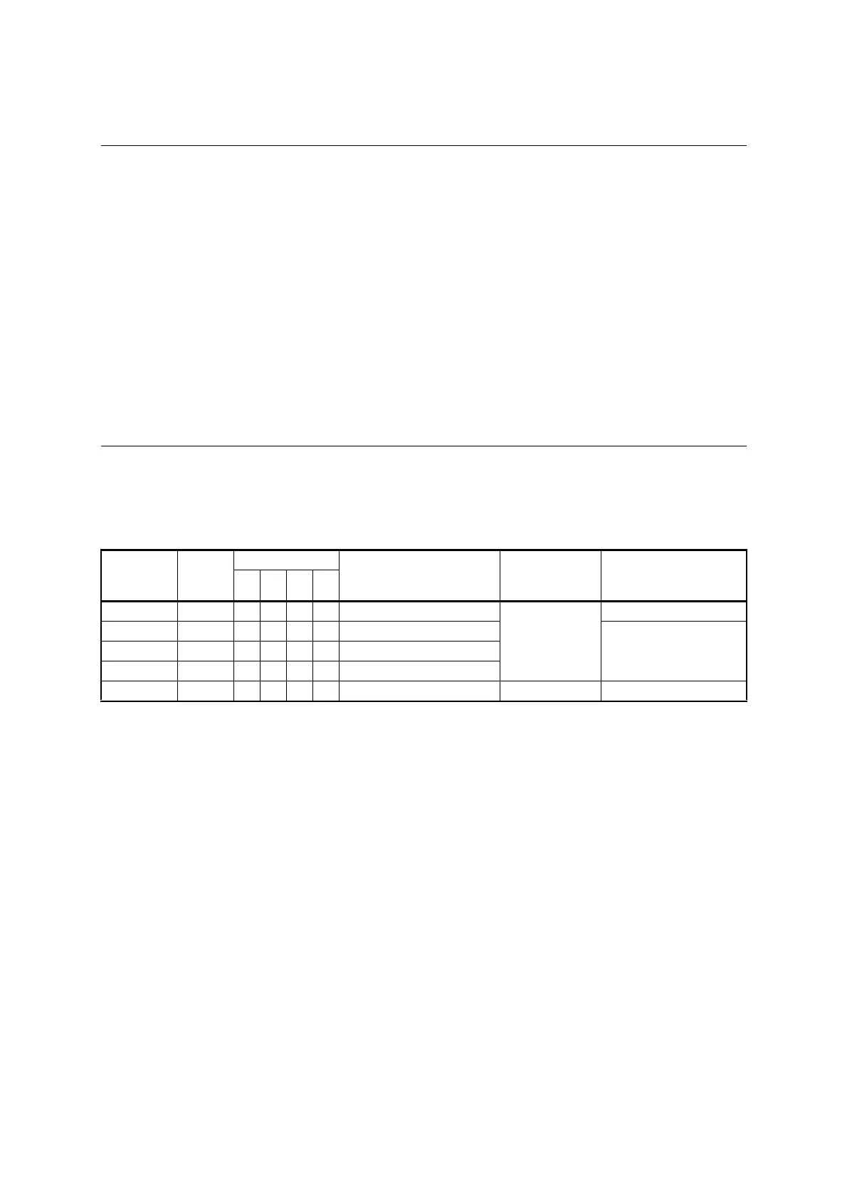
Table 14.4-1 Interrupt Control Bits and Interrupt Sources of Receive Interrupts
Interrupt
request flag
bit
Flag
register
Operating mode
Interrupt source
Interrupt source
enable bit
Interrupt request flag
clear
0123
RDRF SSR ❍❍❍❍Writing received data to RDR
SSR:RIE
Read received data
ORE SSR ❍❍❍❍Overrun error
Write "1" to receive error
flag clear bit (SCR:CRE)
FRE SSR ❍❍
Δ
❍ Framing error
PE SSR ❍ ×
Δ
× Parity error
LBD ESCR ×××❍ LIN synch break detection ESCR:LBIE Write "0" to ESCR:LBD
❍ : Bit to be used
× : Unused bit
Δ
: Usable only when ECCR:SSM = 1