T4
T2
T3
T5
T6
T1
i
F
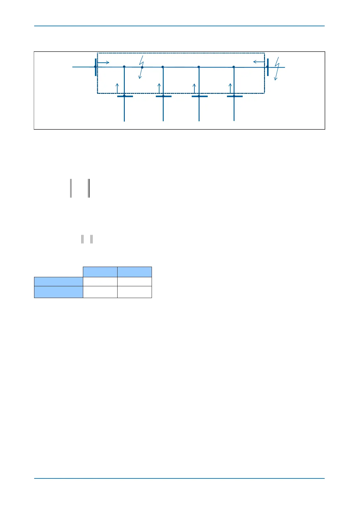
In- zone
F1
F2
i
F
E00761
Figure 32: Sample multi-ended system
The algorithm uses the following differ
ential current and bias current:
● Differential current is the RMS value of the current that is sum of the currents at all ends. For example, in
figure 1, the differential current is defined as:
Where, the “|| ||” symbol means normal operation (RMS value).
● Bias curr
ent is half of the sum of the RMS value of all currents added together.
The difference in I
diff
and I
bias
betw
een internal fault and external fault is shown in the following table:
I
diff
I
bias
Internal fault
IF IF/2
External fault
0 IF
IF is fault current, shown in the diagram above.
2.3.2 DIFFERENTIAL CHARACTERISTICS
The multi-ended line differential characteristic is defined by four settings:
● Phase Is1: The basic differ
ential current setting which determines the minimum pick-up level of the
protection.
● Phase k1: The lower percentage bias setting used when the bias current is below the Phase Is2 setting. This
provides stability for small CT mismatches, while ensuring good sensitivity to resistive faults under heavy
load conditions.
● Phase Is2: A bias current threshold setting, above which the higher percentage bias setting Phase k2 is
used.
● Phase k2: The higher percentage bias setting used to improve protection stability under heavy through fault
current conditions.
Based on the analysis of the discriminative characteristic between internal and external faults, the discriminative
criteria of the differential protection is shown as given below:
I
I K I when I I
I
diff
S bias bias S
S
≥
+ <
1 1 2
11 1 2 2 2 2
+ − + ≥
( )K K I K I I I
S bias bias S
when
Chapter 6 - Current Differential Protection P54A/B/C/E
100 P54xMED-TM-EN-1
 Loading...


