A B
DE
CF
Ch1
Ch1
Ch1
Ch1
Ch1
Ch1
Ch2
Ch2
Ch2
Ch2
Ch2
Ch2
Tx
Tx
Tx
Tx
Tx
Tx
Tx
Tx
Tx
Tx
Tx
Tx
Rx
Rx
Rx
Rx
Rx
Rx
Rx
Rx
Rx
Rx
Rx
Rx
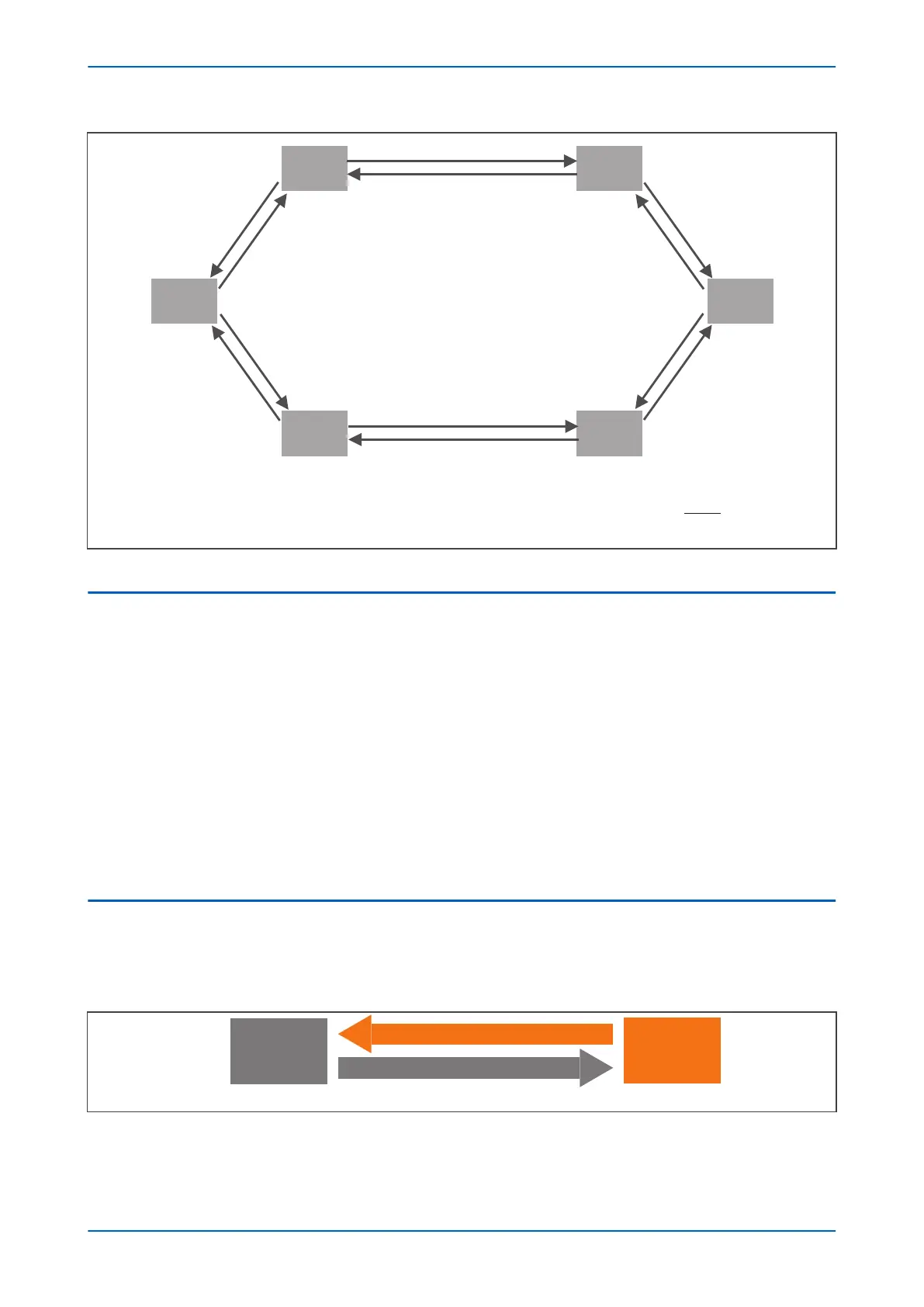
Fixed configuration
3-6 ends, ring connected.always
(optimum performance)
Note the channel allocation (Ch1/Ch2)
E02524
Figure 154: Fibre teleprotection connections for a six-terminal scheme
2.2 PROTECTION COMMUNICATIONS CHANNEL
Multi-ended line differential communications will be using a ring structure.
C37.94 will be the only communication pr
otocol for the protection communications for multi-ended line
differential.
2Mbps E1 will be an additional communication protocol option that will be realised via GE recommended third
party conversion box which will have C37.94 over fibre optic as an input and E1 at 2Mbps over copper as an
output.
For a 6 ended scheme, each terminal will need to communicate with 5 others. This will be done by utilising the
spare slots in C37.94 to pass the data.
Multi-ended line differential communications will have a number of slots in the C37.94 data frame allocated to
each terminals depending on the number of terminals in the scheme.
All the C37.94 slots will be used for all configurations to deliver maximum performance.
2.3 1.1.1.PROTECTION COMMS MESSAGE SLOT ALLOCATION FOR EACH PROTECTION
SCHEME
In most schemes data from each terminal will be available in each communication channel. The multi-end
differ
ential algorithm will use the first valid data received with the correct sequence number from either channel.
Terminal 1
Terminal 2
Terminal 1
Data
Terminal 2
Data
E02525-1
Figure 155: Two terminal single channel scheme
P54A/B/C/E Chapter 15 - Fibre Teleprotection
P54xMED-TM-EN-1 315
 Loading...


