SV Test Mode Setting Result
Disabled
● Normal IED behaviour
● All sampled v
alue data frames received with an IEC 61850 Test quality bit set
are treated as invalid
● The IED will display the measurement values for sampled values with the
Simulated flag set but the protection elements within the IED will be blocked
Enabled
● All sampled v
alue data frames received are treated as good, no matter if they
have an IEC 61850-9-2 Simulated flag set or not
9.2 SIMULATED INPUT BEHAVIOUR
Simulated GOOSE messages and sampled value streams can be used during testing.
The S
ubscriber Sim setting in the COMMISSION TESTS column controls whether a device listens to simulated
signals or to real ones. An IEC 61850 control service to System/LPHD.Sim can also be used to change this value.
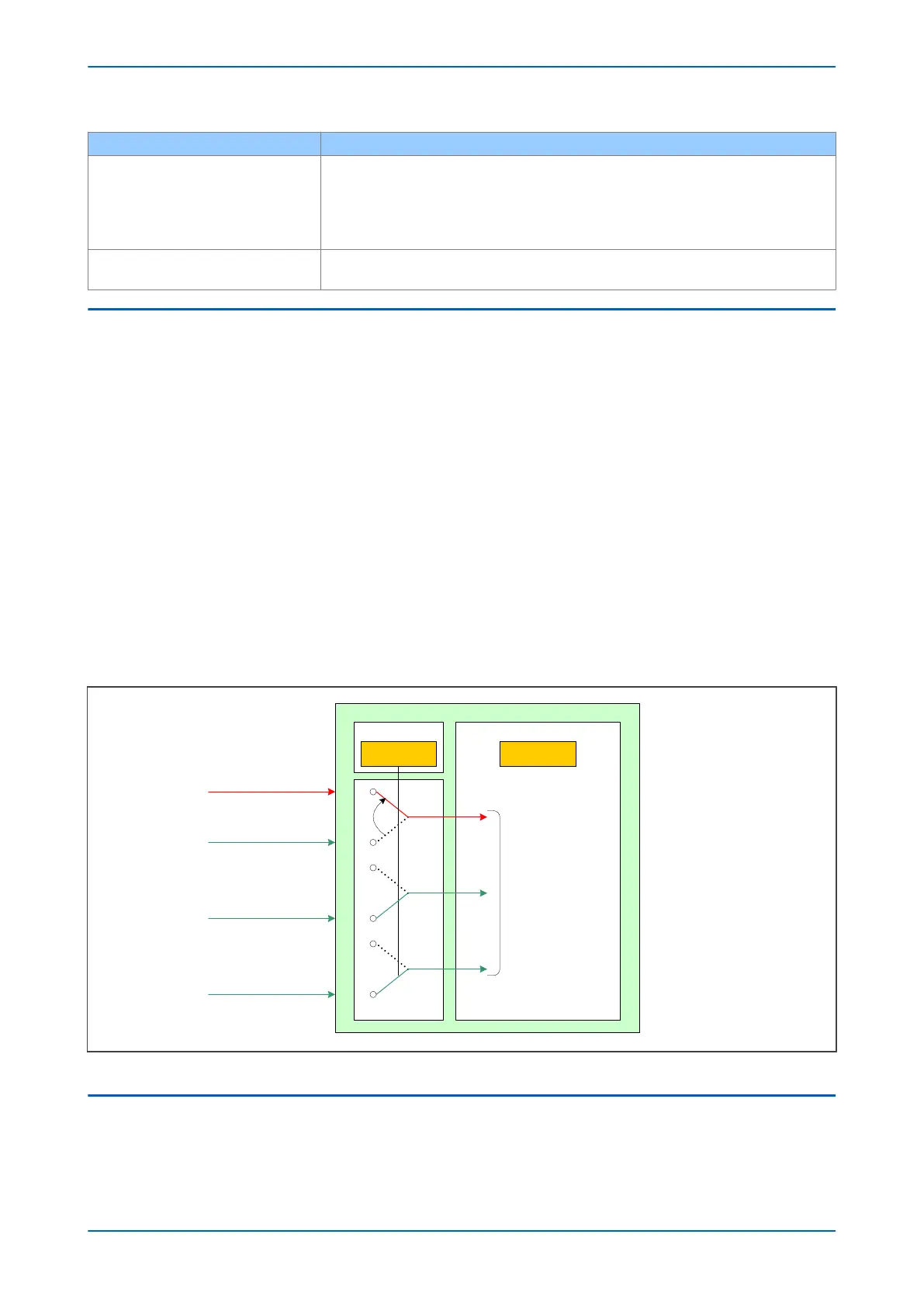
The device may be presented with both real signals and test signals. An internal state machine is used to control
how the device switches between signals:
● The IED will continue subscribing to the ‘real’ GOOSE1 (in green) until it receives the first simulated GOOSE 1
(in red). This will initiate subscription changeover.
● After changeover to this new state, the IED will continue to subscribe to the simulated GOOSE 1 message (in
red). Even if this simulated GOOSE 1 message disappears, the real GOOSE 1 message (in green) will still not
be processed. This means all Virtual Inputs derived from the GOOSE 1 message will go to their default state.
● The only way to bring the IED out of this state is to set the Subscriber Sim setting back to False. The IED will
then immediately stop processing the simulated messages and start processing real messages again.
● During above steps, IED1 will continuously process the real GOOSE 2 and GOOSE 3 messages as normal
because it has not received any simulated messages for these that would initiate a changeover.
The process is represented in the following figure:
Reception buffer
LPHD1
V
01058
Simulated GOOSE 1 messages
S
imulation bit goes TRUE
Real GOOSE 1 messages
S
imulation bit was FALSE
Real GOOSE 2 messages
Real GOOSE 3 messages
Sim stVal=true Beh stVal=on
I
ncoming data
processed
Figure 202: Simulated input behaviour
9.3 TESTING EXAMPLES
These examples show how you test the IED with and without simulated values. Depending on the IED Test Mode, it
may r
espond by operating plant (for example by tripping the circuit breaker) or it may not operate plant.
P54A/B/C/E Chapter 20 - Commissioning Instructions
P54xMED-TM-EN-1 471
 Loading...


