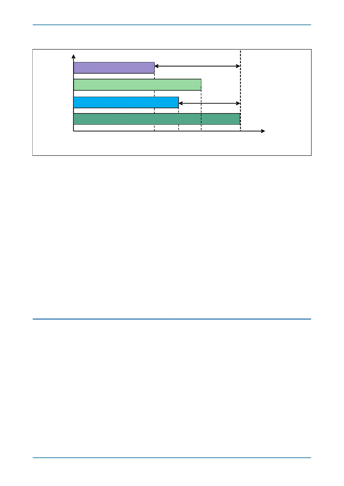
Data from Remote Terminal 1
Data from Remote Terminal 2
Data from Local Terminal
Data from Remote Terminal 3
Terminals
Time
Td1
Td2
Td3
T
0
T
1
T
2
T
3
E00765
Figure 37: Snapshot of available data for processing at each terminal
Fr
om the above figure, it is clear that if we take a snapshot of available data for processing from all the terminals,
the local terminal has the most recent data. Remote terminal 3 has the least amount of data to be processed due
to having the biggest time delay Td3.
To calculate the differential or bias current using the data from all the terminals, it is important to select a time
point where all data is available for all the terminals. In this case, T0 can be selected as reference time to align all
the data as the remote terminal 3 has the largest time delay from local end. Therefore, the currents and voltages
for each terminal will be time aligned according to below:
For local terminal, the delay time is Tdmax = Td3;
For remote terminal 1, the delay time is (Tdmax - Td1);
For remote terminal 2, the delay time is (Tdmax – Td2);
For remote terminal 3, the delay time is (Tdmax – Td3 = 0);
Therefore, the mechanism of time alignment for the multi-ended system is presented as follows:
1. Input all the communication time delay Tp1~Tp5 of all remote ends.
2. Obtain the maximum communication time delay Tpmax = max(Tp1~Tp5).
3. Make the delay time of local data to TdL=Tpmax
4. Make the delay time of data of each remote end to Tdk = Tpmax – Tpk, where, k = 1~5
4.3 TIME DELAY INTERPOLATION
Because the time delay would not always be an integer time of the sample interval, an interpolation of the sample
and time delay ar
e required. The relay will be able to calculate the interpolation based on a mathematical model
derived from the Laplace transform.
After this time-alignment process, the respective differential and bias currents can be calculated.
Chapter 6 - Current Differential Protection P54A/B/C/E
108 P54xMED-TM-EN-1
 Loading...


