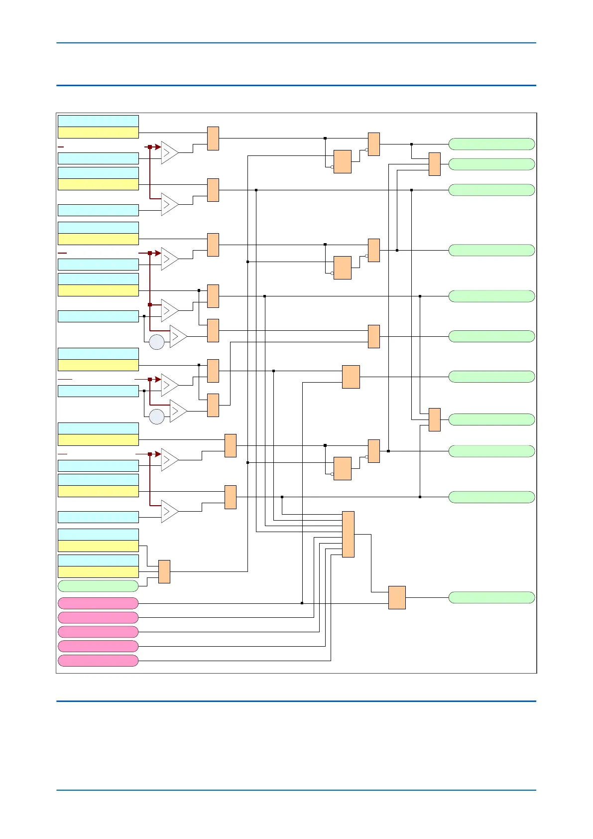
5.6 CB CONDITION MONITORING LOGIC
V01282
CB I^ Maint
I^ Maintenance
Alarm Enabled
&
I^ Maintenance
&
1 CB Monitor Alarm
R
Q
S
I^ Lockout
&
I^ Lockout
Alarm Enabled
CB I^ Lockout
No. CB Ops Maint
Alarm Enabled
&
No. CB Ops Maint
&
R
Q
S
No. CB Ops Lock
&
No. CB Ops Lock
Alarm Enabled
-1
&
Fault Freq Lock
Alarm Enabled
&
Fault Freq Count
R
Q
S
CB FaultFreqLock
-1
&
1 Pre-Lockout
CB Time Maint
CB Time Maint
Alarm Enabled
&
CB Time Maint
&
R
Q
S
CB Time Lockout
&
CB Time Lockout
Alarm Enabled
CB Time Lockout
1 CB Mon LO Alarm
Reset Indication
Yes
Reset CB Data
Yes 1
Reset CB Data
1
Control CB Unhealthy
Control no Check Synch
CB failed to trip
CB failed to close
Reset lockout Alarm R
Q
S
Lockout Alarm
Max no. of CB operations
Greatest broken current total
Fault frequency count
Greatest CB travel time
No. CB Ops Maint
No. CB Ops Lock
Figure 127: CB Condition Monitoring logic diagram
5.7 RESET CIRCUIT BREAKER LOCKOUT
Lockout conditions caused by the circuit breaker condition monitoring functions can be reset according to the
condition of the Rst CB mon L
O by setting found in the CB CONTROL column. There are two options; CB Close
and User interface.
Chapter 12 - Monitoring and Control P54A/B/C/E
256 P54xMED-TM-EN-1
 Loading...


