EasyManuals Logo
Home>GE>Relays>P54C

GE P54C User Manual

GE P54C
850 pages
To Next Page IconTo Next Page
To Previous Page IconTo Previous Page
Page #470 background imageLoading...
Page #470 background image
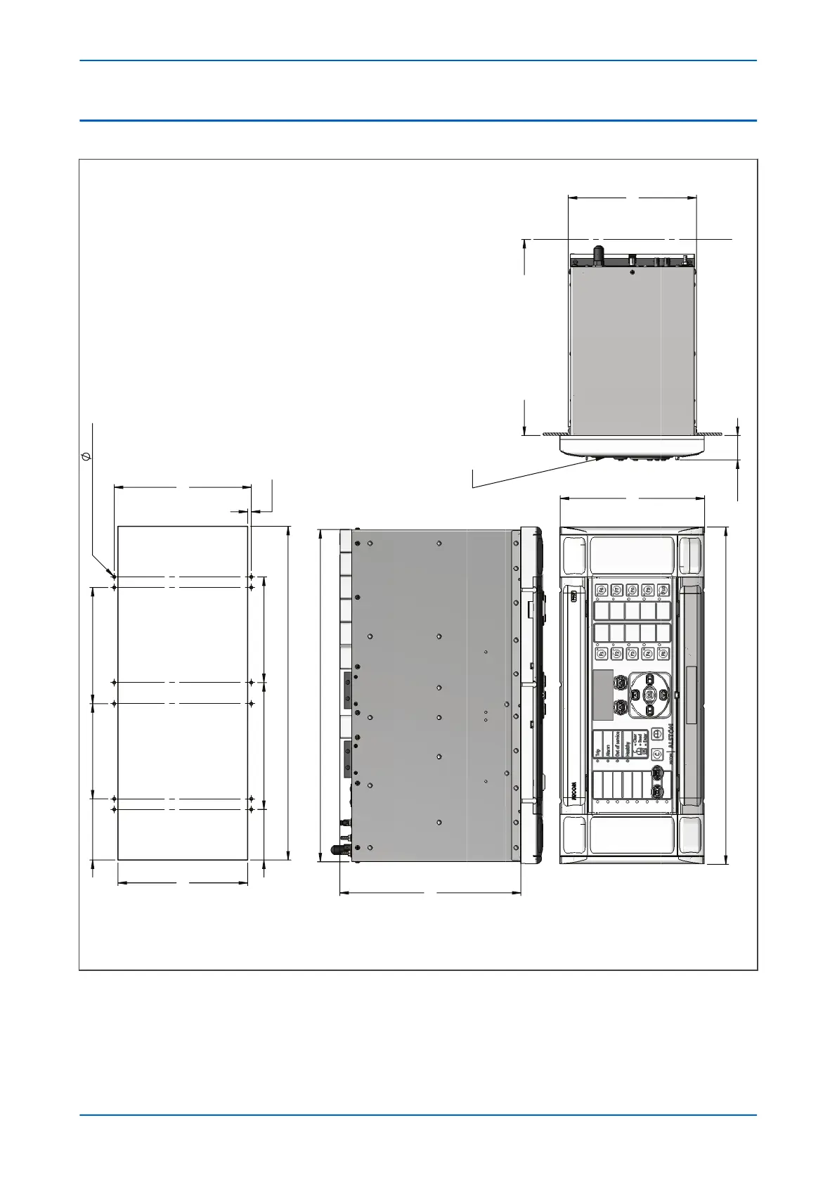
5.3 CASE DIMENSIONS 80TE
413.2
177.00
222.00
407.10
30.00
240.00
INCL. WIRING
157.50 MAX
SIDE VIEW
SECONDARY COVER
(WHEN FITTED)
116.55 142.45
12 OFF HOLES
3.40
168.00
4.50
129.50155.40
408.90
62.00
159.00
74.95
FRONT VIEW
TERMINAL SCREWS : M4 X 7 BRASS CHEESE HEAD SCREWS WITH
LOCK WASHERS PROVIDED.
MOUNTING SCREW : M4 X 12 SEM UNIT STEEL THREAD
FORMING SCREW.
FLUSH MOUNTING PANEL
CUT-OUT DETAIL
E01410
Figure 198: 80TE case dimensions
Chapter 19 - Installation P54A/B/C/E
444 P54xMED-TM-EN-1

Table of Contents

Questions and Answers:

Question and Answer IconNeed help?

Do you have a question about the GE P54C and is the answer not in the manual?

GE P54C Specifications

General IconGeneral
BrandGE
ModelP54C
CategoryRelays
LanguageEnglish

Related product manuals